8
ENGLISH
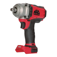
Intended Use
These impact wrenches are designed for professional impact
fastening and drillingapplications.
DO NOT use under wet conditions or in the presence of
flammable liquids orgases.
These impact wrenches are professional powertools.
DO NOT let children come into contact with the tool.
Supervision is required when inexperienced operators use
thistool.
• Young children and the infirm. This appliance is not
intended for use by young children or infirm persons
withoutsupervision.
• This product is not intended for use by persons (including
children) suffering from diminished physical, sensory or
mental abilities; lack of experience, knowledge or skills
unless they are supervised by a person responsible for their
safety. Children should never be left alone with thisproduct.
ASSEMBLY AND ADJUSTMENTS
WARNING: To reduce the risk of serious personal
injury, turn tool off and disconnect battery pack
before making any adjustments or removing/
installing attachments or accessories. An accidental
start-up can causeinjury.
WARNING: Use only Mac Tools battery packs
andchargers.
Inserting and Removing the Battery Pack
from the Tool (Fig. B)
NOTE: Make sure your battery pack
6
is fullycharged.
To Install the Battery Pack into the Tool
Handle
1. Align the battery pack
6
with the rails inside the tool’s
handle (Fig. B).
2. Slide it into the handle until the battery pack is firmly seated
in the tool and ensure that you hear the lock snap intoplace.
To Remove the Battery Pack from the Tool
1. Press the release button
5
and firmly pull the battery pack
out of the toolhandle.
2. Insert battery pack into the charger as described in the
charger section of thismanual.
Fuel Gauge Battery Packs (Fig. B)
Some Mac Tools battery packs include a fuel gauge which
consists of three green LED lights that indicate the level of
charge remaining in the batterypack.
To actuate the fuel gauge, press and hold the fuel gauge
button
10
)
. A combination of the three green LED lights will
illuminate designating the level of charge left. When the level
of charge in the battery is below the usable limit, the fuel gauge
will not illuminate and the battery will need to berecharged.
NOTE: The fuel gauge is only an indication of the charge left on
the battery pack. It does not indicate tool functionality and is
subject to variation based on product components, temperature
and end-userapplication.
Variable Speed Trigger Switch (Fig. A)
To turn the tool on, squeeze the trigger switch
1
. To turn
the tool off, release the trigger switch. Your tool is equipped
with a brake. The chuck will stop when the trigger switch is
fullyreleased.
The variable speed switch enables you to start the application at
a slow speed. The further you squeeze the trigger, the faster the
tool will operate. For maximum tool life, use variable speed only
for starting holes orfasteners.
NOTE: Continuous use in variable speed range is not
recommended. It may damage the switch and should
beavoided.
Forward/Reverse Control Button (Fig. A)
A forward/reverse control button
2
determines the direction of
the tool and also serves as a lock-offbutton.
To select forward rotation, release the trigger switch and
depress the forward/reverse control button on the right side of
thetool.
To select reverse, depress the forward/reverse control button on
the left side of the tool. The centre position of the control button
locks the tool in the off position. When changing the position of
the control button, be sure the trigger isreleased.
NOTE: The first time the tool is run after changing the direction
of rotation, you may hear a click on start up. This is normal and
does not indicate aproblem.
Worklight (Fig. A)
There is a worklight
7
located on the foot of the tool. The
worklight will be activated when the trigger switch isdepressed.
When the trigger is released, the worklight will stay illuminated
for up to 20 seconds. If the trigger switch remains depressed,
the worklights will remainon.
NOTE: The worklight is for lighting the immediate work surface
and are not intended to be used as aflashlight.
Mode Selector (Fig. A, C)
Your tool is equipped with a mode selector
(
8
)
which allows you
to select low, high, or Impact Assist™ mode.
Select the mode based on the application and control the speed
of the tool using the variable speed trigger
(
1
)
.
Impact Assist™ (Fig. C)
In addition to low speed impacting modes, this tool features the
Impact Assist™ mode which grants the user greater control in
both fastening and loosening applications. When set in forward,
the tool will fasten at 2000 RPM until impact begins. The tool
will then pause for 0.5 seconds before continuing to impact at
a rate of 3100 IPM, providing the user with greater control and
reducing the chance of overtightening or damagingmaterial.
When set in reverse, the tool will impact at a normal speed and
rate of 3100 IPM. Upon sensing that the fastener has broken