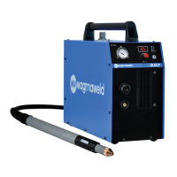
The Magmaweld ID 65 PCA and ID 65 PCB are high-performance inverter plasma cutting machines designed for cutting and gouging applications. Their compact design makes them lightweight and portable, offering excellent cutting and gouging performance.
Function Description
The primary function of these devices is plasma cutting and gouging. Plasma cutting utilizes ionized gas with high electrical conductivity. When the torch trigger is pressed, DC power is activated, and a rapid flow of gas begins in the torch, ionizing the gas and creating a pilot arc. This pilot arc, intensified by the torch, is forced out by high-velocity gases. Upon contact with the metal to be cut, the main current forms, and the cutting process begins, continuing as the torch moves.
A key distinction between the two models lies in their gas pressure adjustment:
- ID 65 PCA: The gas pressure required during cutting is automatically adjusted according to the selected cutting mode and torch type.
- ID 65 PCB: The required gas pressure must be adjusted manually.
Both models offer different cutting modes to adapt to various materials and applications:
- Grid Cut: This mode is specifically designed for cutting materials with gaps, such as grids. When the pilot arc starts, cutting begins, but the pilot arc extinguishes when a gap is encountered. It reactivates when the torch reaches a metal part again, continuing this cycle until the trigger is released. This feature is particularly useful for minimizing the need to repeatedly press the trigger when cutting perforated materials.
- Normal Cutting: In this mode, a pilot arc forms as soon as the trigger is pressed, and cutting begins. The arc will extinguish when the workpiece is finished, even if the trigger is still held. If the trigger is released mid-cut, the arc will also extinguish and will reappear when the trigger is pressed again to continue.
- Torch Trigger Lock: This mode allows the operator to release the trigger after starting the cut, and the cutting process will continue. The pilot arc will extinguish when the workpiece is finished (or a gap is visible), and the mode will deactivate. It reactivates upon pressing the trigger again. This feature simplifies cutting longer workpieces by eliminating the need to continuously hold the trigger.
- Gouging: When the gouging method is selected in automatic mode (for ID 65 PCA), the gas flow rate is automatically adjusted by the machine. For ID 65 PCB, the gas pressure for gouging must be manually adjusted. The torch consumables should be changed to suit the gouging method. A pilot arc forms when the trigger is pressed, and gouging continues along the workpiece until it's finished or a gap is encountered.
Important Technical Specifications
The product labels for both ID 65 PCA and ID 65 PCB indicate the following:
- Mains Voltage (3-Phase 50-60 Hz): 400 V
- Rated Power: 12.3 kVA
- Current Range: 20 - 65 ADC
- Rated Current: 65 ADC
- Open Circuit Voltage: 270 VDC
- Recommended Cutting Thickness (All metals): 22 mm (500 mm/sec.)
- Maximum Cutting Thickness (All metals): 28 mm (250 mm/sec.)
- Breakout Thickness (All metals): 35 mm (125 mm/sec.)
- Gouging (3.5 mm D x 6.6 mm G): 5 kg (1 Hour)
- Dimensions (l x w x h): 628.1 x 219.3 x 453.7 mm
- Weight: 26 kg
- Protection Class: IP21S
The duty cycle, as defined by EN 60974-1, is based on a 10-minute period. For instance, a machine rated at 250A at 60% can cut continuously for the first 6 minutes of the 10-minute period (zone 1), but then requires 4 minutes of idle time for cooling (zone 2).
Usage Features
- User Interface: Both models feature a digital display that visually monitors adjusted welding current, pressure values, pressure graphs, and error codes.
- Adjustment Pot (M/A: Manual / Automatic Mode):
- Automatic Mode (ID 65 PCA): The machine starts in automatic mode without a gas pressure graph visible. The adjustment pot is used solely for current adjustment within specified tolerance ranges. The power supply automatically adjusts gas pressure based on torch type and length, ensuring optimum gas pressure and preventing user errors.
- Manual Mode (ID 65 PCB): Pressing the adjustment pot once switches to manual mode, displaying the gas pressure graph. Both current and gas pressure can be adjusted using the pot.
- Current / Gas Selection Button (ID 65 PCB): This button allows switching between current and gas pressure adjustment tabs in manual mode. Adjustments are made using the adjustment pot.
- Gas Pressure Chart (ID 65 PCB): Graphically displays the gas pressure value. If the graph is empty, the optimum gas pressure (4.8 BAR / 70 PSI) is automatically selected. The pot can be turned right to increase pressure (max 5.5 BAR / 80 PSI) or left to decrease it (min 4.4 BAR / 64 PSI).
- Remote Control: Activated when a mechanized torch is used. A connector at the back of the machine provides access to arc voltage signals for arc transfer and plasma initiation.
- Digital Communication (ID 65 PCA only): An additional socket and card enable digital communication via Modbus. This allows for remote adjustment of current and gas pressure, remote mode changes, and transmission of error codes to the automation interface.
- Analogue Communication (ID 65 PCA & ID 65 PCB): Works with a dry contact structure. The automation unit sends a signal to the plasma machine to initiate a pilot arc. After the pilot arc forms, the plasma machine sends a signal back to the automation unit. During cutting, the plasma arc voltage is reported for height adjustment.
- Voltage Divider Setting: The power supply has a five-position voltage divider (20:1, 21.1:1, 30:1, 40:1, 50:1) to adapt the output voltage to the control system. The default setting is 20:1.
- Torch Usage: To start cutting, push the protective cap on the torch trigger forward and press the trigger. The torch tip should be moved slowly through the material for smooth cutting. When an automation torch is connected, the machine detects it and awaits a trigger from the automation interface, sending necessary data for height adjustment.
Maintenance Features
Maintenance and repairs must be performed by qualified personnel. Using original spare parts is recommended to extend machine life and prevent performance losses.
- Daily Maintenance:
- Regularly check and replace worn or damaged torch consumables. Ensure original products are used for long-term use and high performance.
- Every 3 Months:
- Do not remove warning labels; replace worn/torn ones with new labels obtained from authorized service.
- Check clamps and cables for condition and durability.
- Replace damaged/defective parts. Do not add to or repair cables.
- Ensure adequate ventilation space.
- Every 6 Months:
- Clean and tighten fasteners (bolts and nuts).
- Check workpiece clamp and cables.
- Open side covers and clean the interior with low-pressure dry air or a vacuum cleaner. Avoid applying compressed air directly to electronic components.
- Ensure the air filter is clean; replace it if dirty.
Safety Precautions:
- Always disconnect the power plug and wait 10 seconds for capacitors to discharge before any repair work.
- Never operate the plasma cutting machine with covers open.
- Ensure the power supply is grounded according to national and local electrical regulations.
- Wear dry, insulated gloves, flame-resistant protective clothing, and approved ear protection if noise levels are high.
- Avoid touching live electrical parts or electrodes with bare hands.
- Ensure good metal-to-metal contact for the work clamp, placed as close as possible to the cutting area.
- Do not use AC weld output in damp, wet, or confined spaces, or where there is a risk of falling.
- Long-term inhalation of fumes and gases from welding/cutting is dangerous. Ensure adequate ventilation or use fume extraction systems and breathing apparatus in confined spaces.
- Moving parts can cause injuries; keep all protective devices closed and locked.
- Sparks and spattering particles can cause eye damage; wear approved protective goggles under welding masks.
- Hot parts can cause severe burns; allow the machine to cool, or use appropriate tools and protective clothing when handling hot parts.
- Welding wires can cause injuries; do not point the torch at anyone or any metal while unwrapping wire.
- Welding operations can cause fire and explosion; never work near flammable materials.
- Maintenance by unauthorized persons can cause injuries.
- Electromagnetic interference (EMF) can affect electronic devices and medical implants. Follow procedures to minimize EMF exposure, such as assembling and securing cables, and keeping the operator's body and head away from the machine and cables.
- The device is not domestic waste and must be recycled according to EU directives and national laws.