C-61
35 Series 4WD, Model - 3535, 4035, 4535 and 5035 SM June’08
4. Check the crankshaft end float
a) Assemble the crankshaft with the main
bearings in position.
b) Lever the crankshaft towards the front of the
engine so that the thrust face is tight against
the rear thrust flange of the rear main bearing.
NOTE: Bearing cap bolts should be slackened off
slightly to facilitate this operation.
If the clearance is excessive the rear main
bearings must be replaced.
D. THE CRANKSHAFT
1. Examine the journals for excessive scoring.
2. Measure the diameter of each journal at
various points to check any out of round
tendencies. If the journals are excessively worn
it will be necessary to re-grind the crankshaft
and fit undersize bearings. Limits for undersize
grinding are given in fig. 7.
NOTE: Maximum allowable taper on crank pins
and journals is 0.00015” per inch of length.
Crank pins and journals must be polished
and must not be more than 0.00015” out
of round. Run-out on centre main bearing
journals must not exceed 0.0008”, total
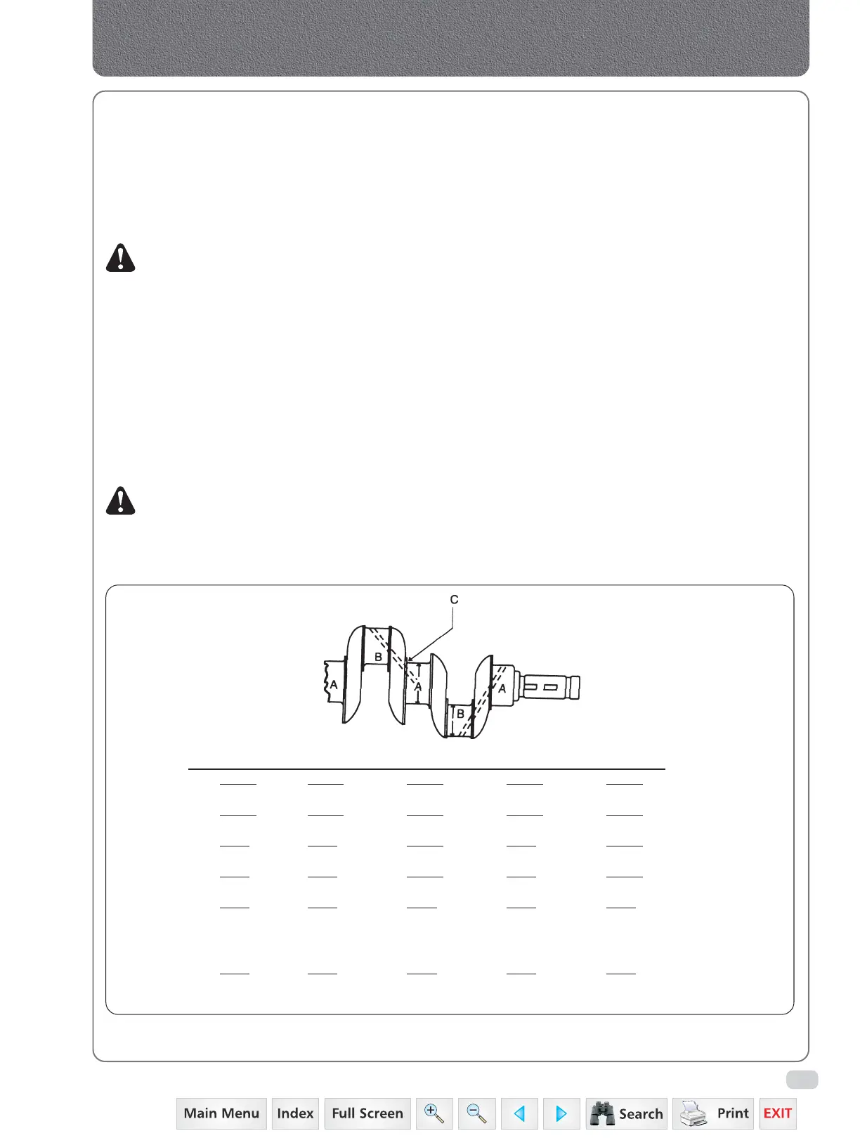
Fig. 7
Undersize Limits for Crankshaft Regrinding
DIM STANDARD 0.010” U/S 0.015” U/S 0.020” U/S 0.030” U/S
1.
2.1247 2.1147 2.1097 2.1047 2.0947
2.1257 2.1157 2.1107 2.1057 2.0947
2.
1.7502 1.7402 1.7352 1.7301 1.7202
1.7507 1.7407 1.7357 1.7307 1.7207
3.
1.314 1.319 1.3215 1.324 1.3200
1.316 1.321 1.3235 1.326 1.3310
4.
2.420 2.422 2.4240 2.420 2.4200
2.432 2.436 2.4360 2.438 2.4390
5.
0.125 0.125 0.125 0.125 0.125
0.135 0.135 0.135 0.135 0.135
6. MUST BE CONCENTRIC WITHIN 0.004” T.I.R.
7. These holes must be clean and free of chips and burrs after grinding. Remove sharp edges.
8.
1.313 1.316 1.321 1.323 1.328
1.317 1.322 1.325 1.327 1.332
Permissible width of all Main Journal and Crank Pins except at No. 5 Journal ‘C’ listed above.
indicator reading with the shaft mounted
on V blocks at the front and rear journals.
3. Examine the clutch shaft pilot bearing for
excessive wear or corrosion. If necessary pull
the bearing from the crankshaft and replace
with new.
4. Examine the flywheel dowels for wear and
looseness of fit. If necessary press in new
dowels to the dimensions shown in fig.5.
5.
Ensure that the oil ways in the crankshaft are clear.
1. REMOVAL
a) Place the special tool (3-6) into the insert and
turn in an anti-clockwise direction. Never
reuse an insert which has been removed.
2. INSTALLATION
a) Fit a new insert (2-6) into the driver (1-6) with
the driving lug to the bottom.
b) Screw the insert into the tool guide until it
is flush with the end of the tool.
c) Place the inserting tool over the tapped hole
in the crankcase and turn the handle in a
clockwise direction until the insert leaves the
tool. Care must be taken not to drive the insert
in too deeply (refer to SPECIFICATIONS).
Crankcase, Crankshaft, Main Bearings & Flywheel
 Loading...


