C-60
35 Series 4WD, Model - 3535, 4035, 4535 and 5035 SM June’08
2. Inspect the crankcase for trueness, using the
crankshaft as follows :
a) Wipe the bearing supports of the crankcase
free of oil with a lint free cloth.
The crankcase should be bottom side up and
levelly supported.
b) Install the upper halves of the bearings to
the crankcase. If the original bearings are
being reinstalled, ensure that they are fitted
to the positions from which they were
removed. The location nibs of the bearings
must fit into the notches in the main
bearings supports.
c) Smear blueing on the crankshaft main
journals and lower it carefully and evenly
on to the bearings. Do not install the bearing
caps and lower bearings.
d) Rotate the crankshaft back and forth
through approximately 180
0
, remove the
crankshaft evenly and inspect the upper
bearing for an even transfer of blueing from
the journals to the bearings.
1) Any bearings that do not show all over
even blueing should be replaced by new.
It is advisable to replace all bearings by
new ones if an original one is faulty.
2) Clean the blueing off the crankshaft and
bearings.
3) Checking main bearing running
clearance.
4) Install the upper bearing halves.
5) Place the crankshaft in position.
6) Lay a length of plastigauge along the
crankshaft journals.
7) Fit the bearing lower halves to the
bearing caps and assemble the caps to
the crankcase.
e) Fit the capscrews and tighten to the torque
detailed in SPECIFICATIONS. Do not rotate
the crankshaft.
f) Remove the bearing caps and measure the
thickness to which the plastigauge has been
crushed. This thickness should be as detailed
in SPECIFICATIONS.
g) If the clearance is excessive, it may be
necessary to grind the crankshaft and install
undersize bearings. These bearings are
available in sets of +0.030” and +0.015”.
See para. 3c for details of re-grinding
crankshaft.
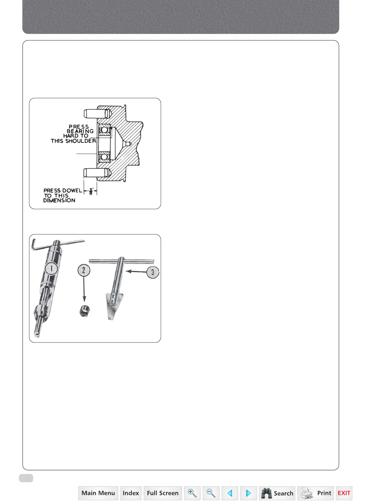
Fig. 5
PILOT
BEARING
Fig. 6
Crankcase, Crankshaft, Main Bearings & Flywheel
 Loading...


