C-59
35 Series 4WD, Model - 3535, 4035, 4535 and 5035 SM June’08
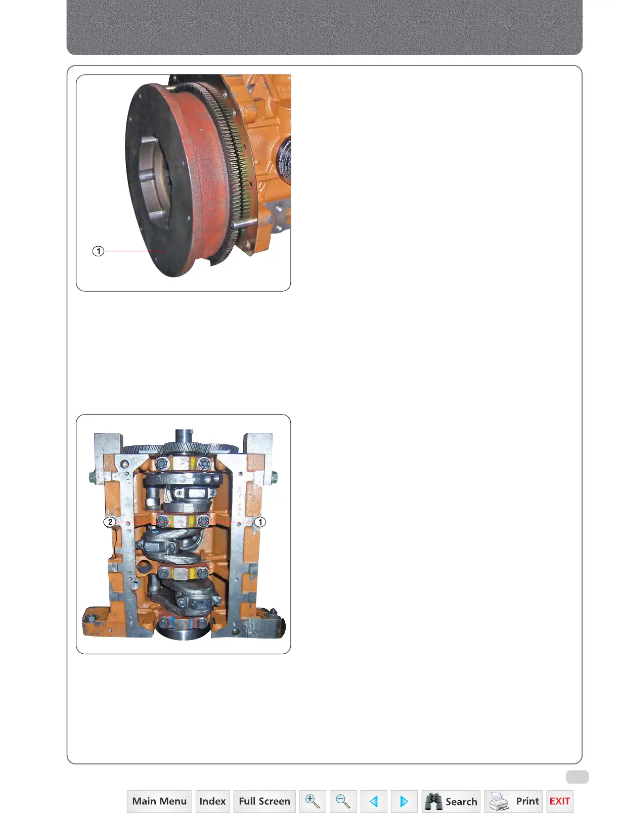
3. INSTALLATION
a) Install the flywheel on the crankshaft lining up
the dowel holes.
b) Install the bolts and tab washers then tighten the
bolts to the specified torque.
c) Mount a dial indicator on the crankcase and check
that friction face run-out does not exceed 0.001 inch
per 1-1/2 inches of radius. If run-out exceeds this
figure remove the flywheel and check the
mounting faces on the flywheel and check the
mounting faces on the flywheel and crankshaft
for burrs or foreign matter.
d) If run-out is within the figure in op. (c) bend up
the tabs to secure the bolts. On current engine
the locktabs are deleted.
C. CRANKSHAFT BEARINGS AND CRANKSHAFT
1. REMOVAL
a) Crankshaft removal required removal of engine
from tractor.
b) Remove the clutch, flywheel.
c) Remove the timing cover.
d) Invert the engine.
e) Remove oil pan and adapter plate.
f) Remove the rear oil seal retainer by removing
7 cap screws (2-1).
g) Remove the bearing cap bolts (1-4).
Then remove the bearing caps (2-4) and bearing
inserts and identify them if them if they are to
be re-used.
h) Lift the crankshaft from cylinder block and remove
the bearing inserts.
2. INSPECTION AND REPAIR
a) Clean all parts in a suitable solvent and dry with
compressed air.
b) Discard the front and rear oil seals. Discard all
gaskets and remove any gasket material remaining
on mating faces.
c) Check in the crankcase for sludge deposits.
These should be removed and the crankcase
thoroughly cleaned.
d) Use liquid gasket (loctite 584) on crankcase,
adapter and oil pan joints.
3. THE BEARINGS AND CRANKCASE
1. Inspect the bearings for wear and evidence of
uneven bearing support. If such evidence is
present, examine the bearing caps and supporting
surfaces of the crankcase for high spots and burrs.
Fig. 2
Crankcase, Crankshaft, Main Bearings & Flywheel
Fig. 4
 Loading...


