E-33
35 Series 4WD, Model - 3535, 4035, 4535 and 5035 SM June’08
Differential
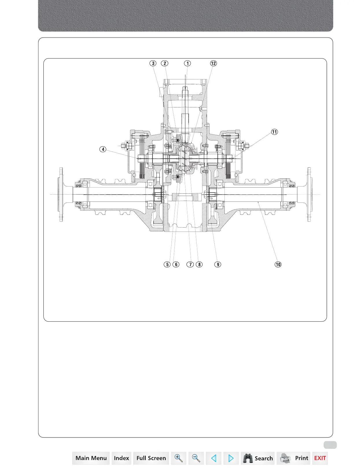
1. Theory of Operation
The power from Spline Shaft (1) drive the Gear Crown
Wheel (6). This in turn rotate Differential Housing (12).
The power from differential housing flows through
differential pinion (2) and then to Bevel Gear Differential
(5/8). Bevel Gear drives the Bull Pinion (4/11). The Bull
Pinion Shaft end matches with Bull Gear (9). This results
in rotation of Axle Shaft (10).
The Differential Housing Assembly consists of two Bevel
Gear (LH & RH), two pinion and one shaft.
When tractor takes a turn, one axle moves faster than
other. This results in rotation of differential pinion to
rotate on it’s own axis, and they roll over bevel gear
and thus producing differential action.
DIFFERENTIAL LAYOUT
1. Spline Shaft
2. Pinion Differential Case
3. Differential Case
4. Bull Pinion Brake Shaft LH
5. Bevel Gear Differential LH
6. Gear Crown Wheel
7. Differential Pinion Shaft
8. Bevel Gear Differential RH
9. Bull Gear
1
0
.
12. Differential Housing Assembly
A
x
l
e
R
e
a
r
11. Bull Pinion Brake Shaft RH
 Loading...


