E-34
35 Series 4WD, Model - 3535, 4035, 4535 and 5035 SM June’08
Differential
2. Description
The differential is located in the rear housing and is
mounted on two taper roller bearings. The drive bevel
(ring or crown) gear is bolted to the differential case
LH side.
The taper roller bearing is preloaded by shims located
between the differential cage and sides of the rear
housing, determine the backlash between the bevel gear
and the drive pinion and preload on the taper roller
bearings support that the differential.
Adjustment of the drive pinion and bevel gear tooth
contact is obtain by graded spacer between transmission
splined shaft bearing head and machine surface of the
housing.
The differential lock unit is incorporated which is
controlled by a foot pedal as assembled at the right
hand.
The differential gear assembly is a mechanism to provide
smooth steering. It automatically provides relative speed
to both rear wheels according to road resistance and
braking friction at the wheel.
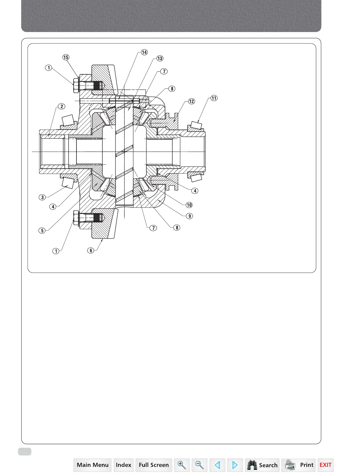
Layout of Differential Assembly
1. Bolt
2. Bush Bull Pinion Shaft Support
3. Taper Roller Bearing
4. Thrust Washer Bevel Gear
5. Bevel Gear Differential LH
6. Gear Crown Wheel
7. Thrust Washer Bevel Pinion
8. Pinion Differential
9. Differential Case
10. Bevel Gear Differential RH
11. Taper Roller Bearing
12. Coupling
13. Shaft Differential Pinion
14. Pin Spring Differential
15. Lock Plate Bolt Diff. Case
 Loading...


