E-47
35 Series 4WD, Model - 3535, 4035, 4535 and 5035 SM June’08
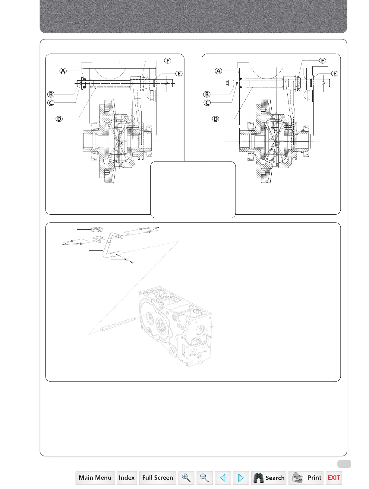
1. Theory of operation :
When differential lock pedal is pressed down, the differential lock shaft is rotated. The wedge action
of fork differential lock due to rotation of shaft along with spring dowel, moves fork axial against
spring. This motion presses the spring. Thus differential fork moves towards differential case.
Differential lock coupling moves towards the differential case. When the differential lock coupling
pins, aligned with the holes on the bevel gear, get inserted into the bevel gear.
Since the bull pinion shaft is coupled with spline bevel gear, no differential action takes place and
both bull pinion shaft rotate with equal RPM.
DIFFERENTIAL LOCK DISENGAGED POSITION
DIFFERENTIAL LOCK ENGAGED POSITION
Differential Lock System
EXPLODED VIEW OF DIFFERENTIAL LOCK PEDAL LINKAGES
A. Oil Seal
B. Differential Lock Shaft
C. Spring Dowel Sleeve
D. Spring
E. O’ Ring
F. Spring Dowel
4
5
1
2
3
6
7
1. Diff Lock Pedal
2. Foot Plate Differential Lock
3. Rubber Boot Differential Lock Pedal
4. Spring Dowel Pin Outer - RSL
5. Spring Dowel Pin Inner - RSL
6. Bolt Flanged M6 X 1.0 X 30
7. Nut M6 X 1
 Loading...


