G-21
35 Series 4WD, Model - 3535, 4035, 4535 and 5035 SM June’08
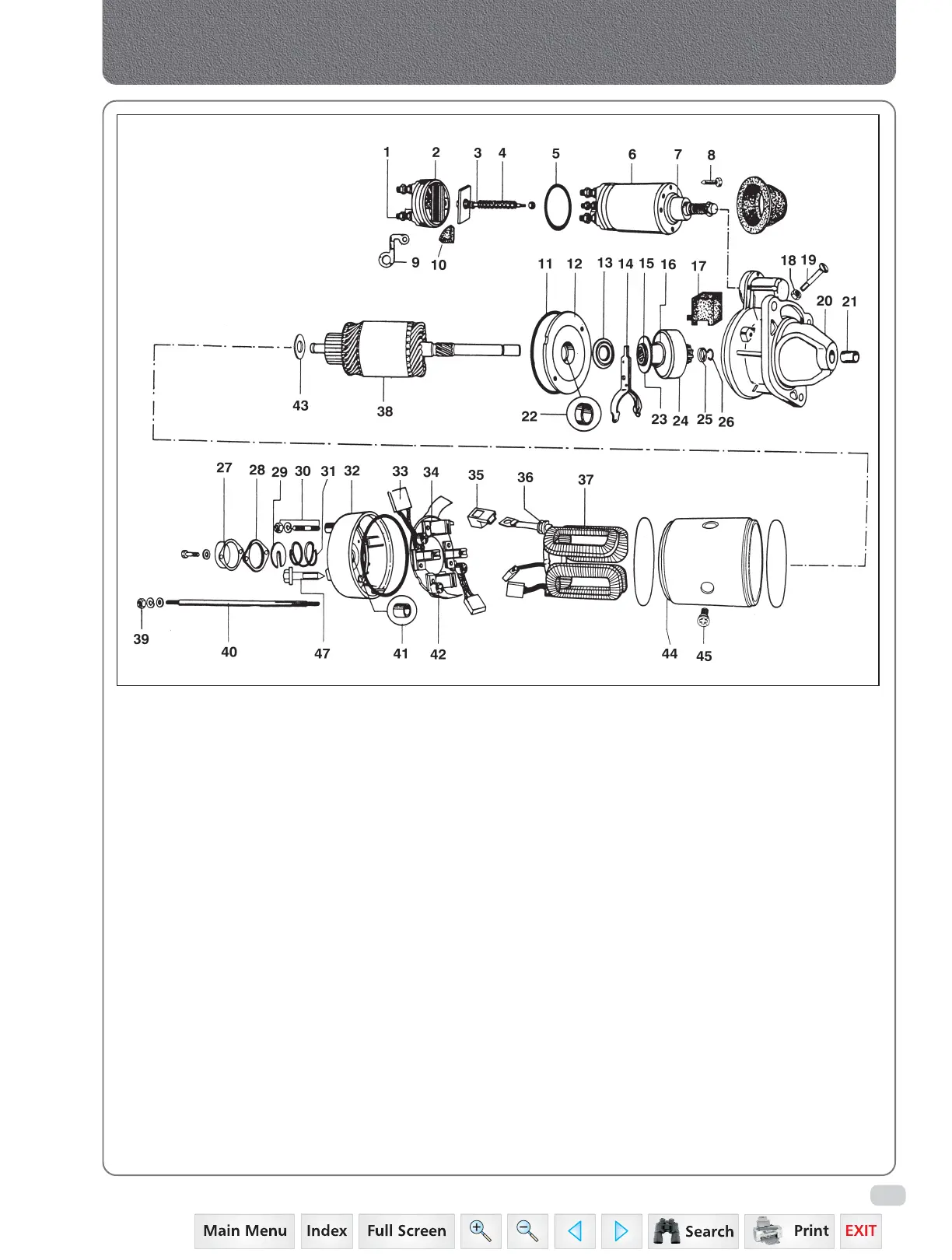
Electrical System
1 Main Terminal (Sol.)
2 Terminal Base Assy.
3 Spindle Assembly
4 Plunger Return Spring
5 Sealing Ring (Sol.)
6 Solenoid Switch
7 Plunger Assembly
7A Shroud
8 Screw (Sol. Fixing)
9 Connector
10 Seal
11 Sealing Ring (C.E. & D.E.)
12 Intermediate Brkt. Assy.
13 Oil Seal
14 Engaging Lever Assembly
15 Jump Ring (Pinion)
16 Spring (Pinion)
17 Grommet
18 Nut (Pivot)
19 Pivot Pin
20 Fixing Bracket Assembly
21 Bearing Bush (Fag. Bakt.)
22 Bearing Bush (Inter Bakt.)
23 Operating Plate (Pinion)
24 Drive Assembly
25 Thrust Collar
26 Jump Ring
27 End Cover
28 Seal (End Cover)
29 "C" Washer
30 Earth Terminal
31 Spring (End Cover)
32 C.E.Bracket Assembly
33 Brush Set
34 Brush Carrier Assembly
35 Lead Assembly
36 Grommet
37 Field Coil Assembly
38 Armature Assembly
39 Nut (Fixing Stud)
40 Fixing Stud
41 Bearing Bush (C.E. Brkt.)
42 Brush Spring
43 Stop Washer
44 Insulator Yoke
45 Pole Screw
46 Rear Bracket Assy.
47 Screw (B.G. Fixing)
Fig. 3
Exploded view of Starter Motor
 Loading...


