G-22
35 Series 4WD, Model - 3535, 4035, 4535 and 5035 SM June’08
Electrical System
c. Tooth to Tooth Abutment
When the tooth to tooth abutment takes place the
plunger movement is restricted because the drive
movement is restricted. But the plunger is so designed
that it can move in further closing the contacts
connecting the starter to battery. When starter rotates,
the pinion gets slipped into mesh by the force of the
compressed engaging spring.
d. The Lost Motion Device
A feature of ‘Lost Motion’ is designed into engagement
mechanism to allow the solenoid contacts to open
before pinion retraction begins. This action depends
upon the yielding of a weaker spring which forms the
lost motion device, to the stronger system return spring
of the plunger. The lost motion spring is carried in the
plunger. The initial yielding results in the switch contacts
being fully opened within the first 3.20 mm of plunger
return travel- this action being followed by normal drive
retraction.
3) Routine Maintenance
1) Ensure that the mounting bolts are securely
fastened and all electrical connections are clean
and tight.
2) Cables should be examined for fractures.
b. Solenoid Relay
The solenoid relay is mounted on the DE bracket
with its axis parallel to that of armature. This
contains a soft iron plunger, a pair of heavy
duty copper studs forming fixed contacts, a
moving contact made up of copper is carried
on a non-magnetic spindle which is insulated
to the contact plate. This also moves the drive
assembly with the help of a lever and peg
assembly which is pivoted on an eccentric pin
screwed on the DE bracket. The electrical circuit
diagram given below explains the connections
of solenoid winding. The coil consists of two
windings, a heavy gauge which is called pull-
in or series winding and a thinner gauge
winding called hold-on or shunt winding. The
pull in winding is connected through the field
coil and armature to the ground. Whereas shunt
is connected between smaller terminal on the
solenoid phenolic moulded terminal base and
ground. When the switch is closed both pull
in and hold on windings get energised resulting
in pulling in of plunger. At the end of the travel
the main contacts get closed, connecting starter
to battery. Simultaneously series winding gets
short circuited between main contacts.
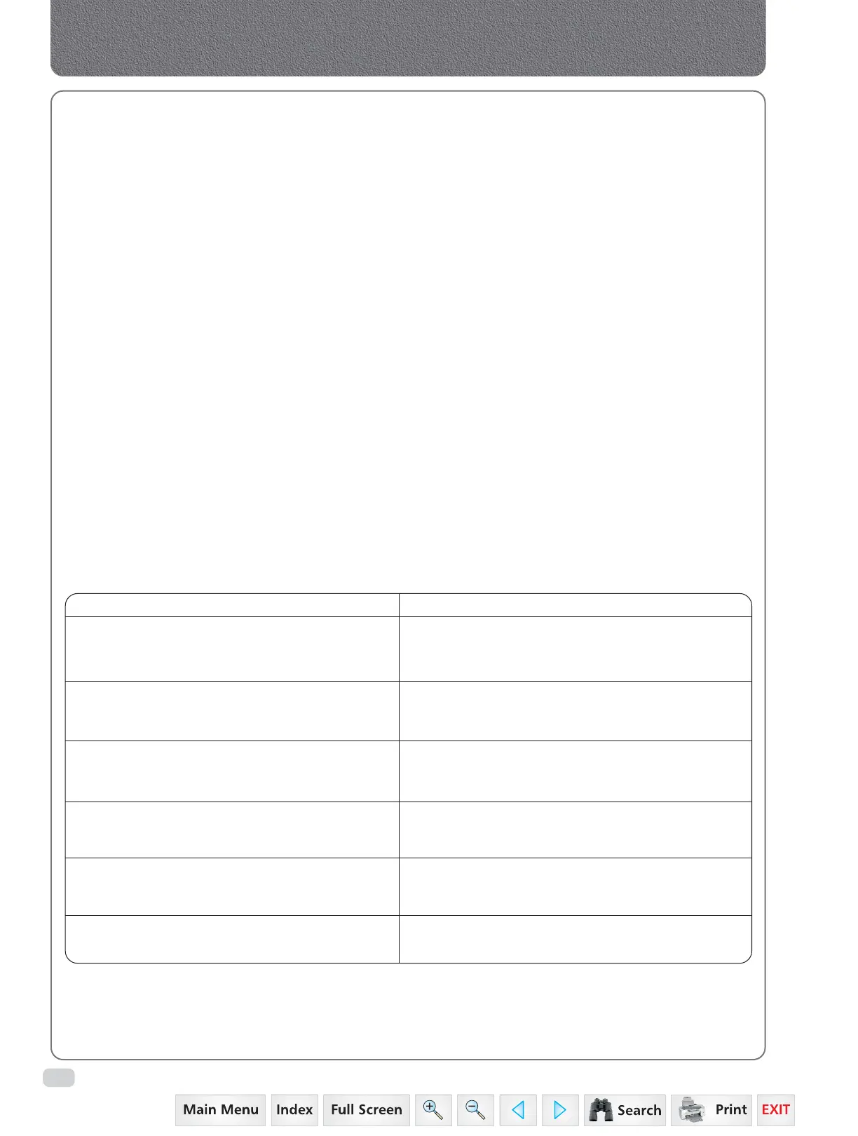
4) STARTER MOTOR DO’S AND DONT’S
DO’s DONT’s
Ensure that all electrical connections in the Do not operate the starter motor when the engine
circuit including the battery are clean and is running as this could result in
secure. damaging the starter motor and flywheel ring gear.
Observe correct polarity, i.e. connect Do not crank continuously. If the engine does not
negative to negative and positive to positive. fire immediately, allow sometime to cool the
starter motor before cranking again.
For earth return system, a twin wiring system If still the engine does not start, ascertain the
between battery and starter motor should be cause and do not drain the battery by cranking
used. the starter motor.
The total resistance of the starter circuit Do not inch (move) the vehicle using starter motor.
including that of return path and junctions
should not exceed 0.002 Ohm 20
0
C.
The main feed cable should be supported to Do not disconnect battery cables while the
prevent the cable weight and vibrations from engine is running.
coming on to the electrical terminals.
While washing the vehicle with high pressure Do not subject the starter motor to continuous
gun starter motor should be suitably protected. oil / water drip.
ROUTINE MAINTENANCE
• Ensure that the starter motor mounting bolts are securely fastened.
• Check and ensure that all electrical connections are firmly tightened.
• Examine cables for fractures / cracks particularly at the terminal lugs.
 Loading...


