I-7
35 Series 4WD, Model - 3535, 4035, 4535 and 5035 SM June’08
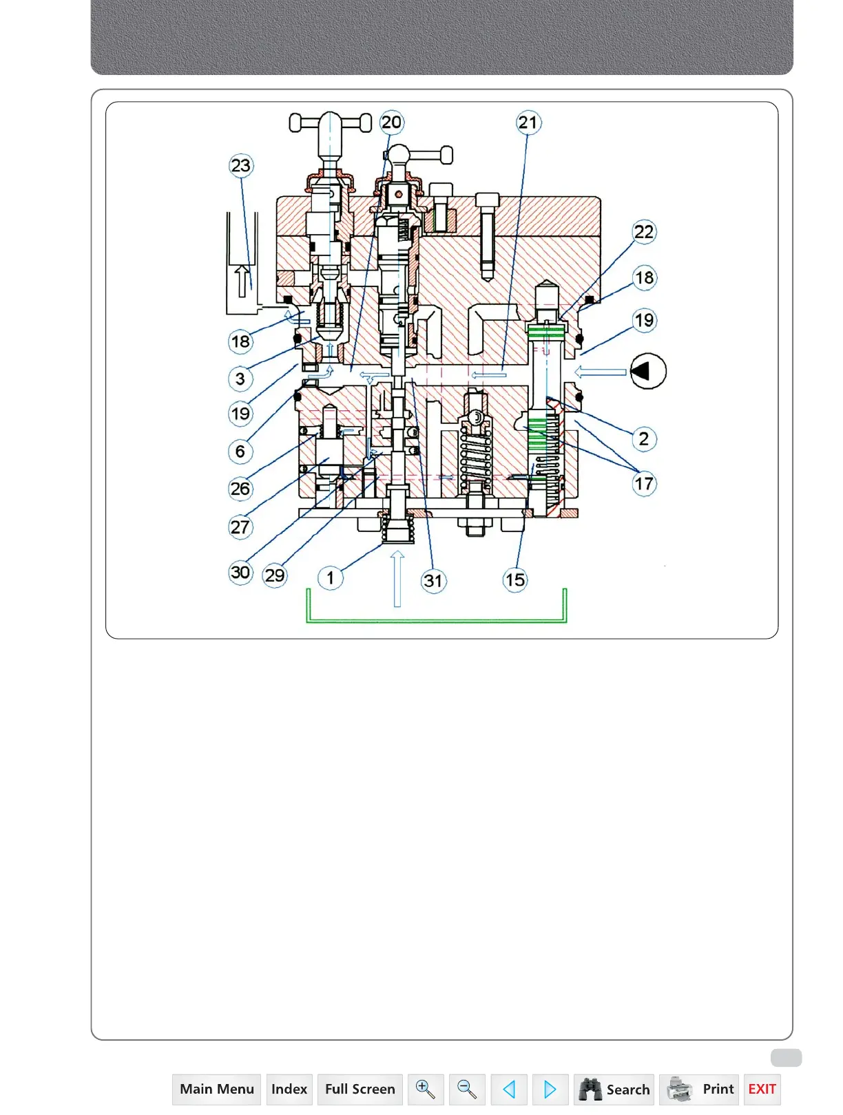
B. DELIVERY PHASE
During this phase the Control Valve supplies oil
under pressure to the cylinder (23) and this
consequently lifts the arms.
The control spool (1) is in the position to connect
chamber (26) of the pilot valve (27) with the oil
coming from the pump through the annular duct
(19) and the holes (20), (21) and (30) thus
allowing the pilot valve to close itself. The oil
coming from the pump feeds at the same
pressure chamber (22) and chamber (15)
(through duct - 29) of the regulator piston (2)
that closes the discharge holes (17) due to the
upward push of the return spring.
The oil under pressure flows to the cylinder
through the annular duct (19, enters in hole (20)
through the fixed throat (6) and the variable
throat made by the control spool (1) with the
hole (21), opens the check valve (3), enters in the
annular duct (18) and feeds chamber (23) of the
cylinder.
The regulator piston (2) regulates the oil flow of
the cylinder because chambers (15) and (22) are
subject to the difference in pressure created by
the oil in the passage through the variable throat
(31) which is opened or closed by the control
spool (1).
The excessive flow Is deviated on the rising
pressure from holes (17), thus regulating the
maximum lifting speed and allowing a slow and
smooth starting and arrival of the lifting arms.
The maximum lifting pressure is controlled by a
relief valve placed on the body of rock shaft
connected to the inlet port of oil coming from
the pump.
Hydraulics
 Loading...


