I-8
35 Series 4WD, Model - 3535, 4035, 4535 and 5035 SM June’08
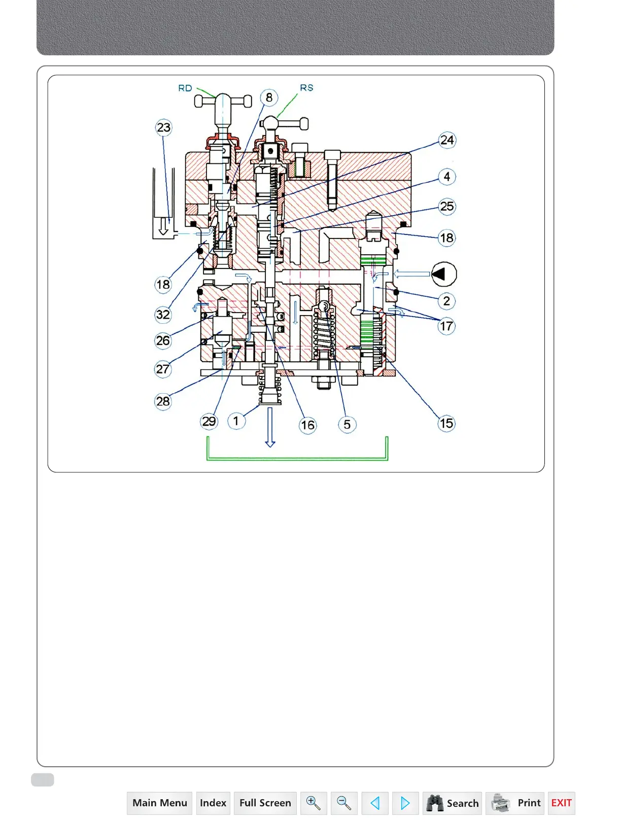
C. DISCHARGE PHASE
During this phase the Control Valve supplies to
the discharge both the oil coming from the pump
as well as the oil coming from chamber (23) of
the cylinder, with the consequential lowering of
the lifting arms.
The control spool (1) is in the position to connect
chamber (26) of the pilot valve (27) directly to the
discharge through hole (16), thus allowing the
same valve to open hole (28) that flows to the
discharge through duct (29) chamber (15) of the
regulator piston (2). The oil coming from the
pump, as in the neutral phase, is able to move
the regulator piston towards chamber (15) that
opens the discharge holes (17) causing oil to flow
to the tank.
At the same time the oil from the cylinder under
pressure (chamber - 23) enters in the annular
duct (18) passes through the holes (32), the valve
(8) and hole (24) enters in the discharge valve (4)
flowing to the tank from hole (25), causing the
lowering of the arms.
In this phase the lowering speed of the arms can
be regulated by the manual lever "RD" (by
screwing the lever clockwise the lowering speed
decreases).
For road transport, in order to avoid the
accidental lowering of the rockshaft arms due to
the movement of the levers, screw shut the lever
"RD", this completely closes the valve (8) in its seat
in order to close the passage between the
chamber (23) of the cylinder and the discharge
valve (4).
The cylinder is always protected by accidental
over-pressure by the safety valve (5).
Hydraulics
 Loading...


