I-9
35 Series 4WD, Model - 3535, 4035, 4535 and 5035 SM June’08
5. HOW THE INTERNAL LEVERAGE SYSTEM FUNCTIONS
a. FUNCTIONING OF POSITION CONTROL
b. FUNCTIONING OF DRAFT CONTROL
c. COMBINED FUNCTIONING OF POSITION
AND DRAFT CONTROL
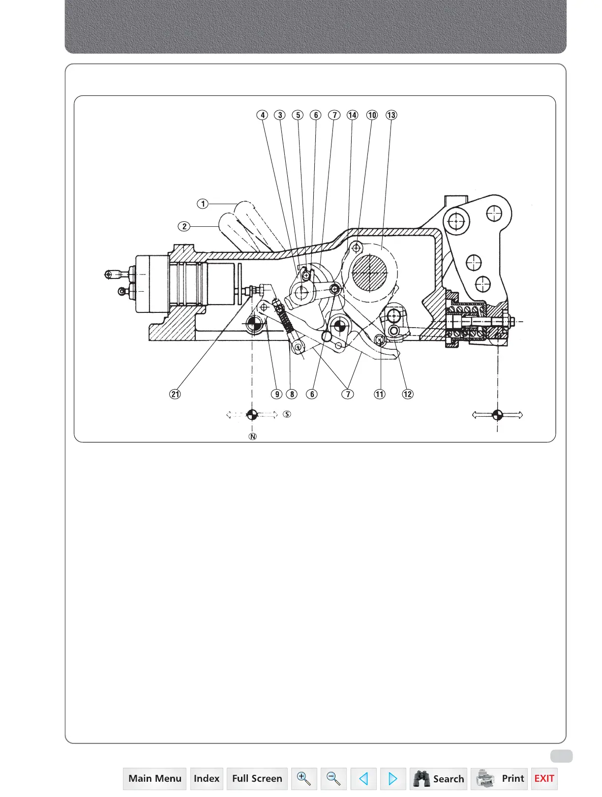
A. FUNCTIONING WITH POSITION CONTROL
By positioning the draft control lever (2) against
the backstop (E) the roller (11), which slides on
the flywheel (7) of draft cam (12), will be moved
away completely.
In this way the draft levers will not in any way
interfere with the operation of the position
control. The arms are raised by moving the
position control lever (1) upward, and the
leverage system will act in the following way:
Crank (4) being an integral part of shaft (3) turns
in a clockwise direction and causes roller (5) to
slide on the position cam (6), in turn causing the
clockwise rotation of flywheel (7). The flywheel
will transmit an anticlockwise rotation, by means
of friction shock absorber (8), to the transmission
lever (9) that will bring distributor shaft (21) into
delivery position (C), thus causing the arms to
be lifted.
During the lifting movement of the arms, crank
(13) with pin (10) will rotate in an anti-clockwise
direction, and by means of the link (14) will cause
position cam (6) to rotate clockwise.
When the roller (5) meets the inclined plane of
the cam (6), it allows the anti-clockwise rotation
of the flywheel (7) that by means of a friction
shock absorber (8) rotates the lever (9) in a
clockwise direction, which is pushed by the spring
of the control valve shaft (21) which moves to
position (N) (neutral phase) and thus blocking
the movement of the lifting arms.
During the lowering phase of the arms the
movements of the levers indicated above will
occur in the opposite sense.
The position of the arms, during lifting and
lowering, correspond to a specific position of the
position control lever (1).
Positive
Stroke
+
Negative
Stroke
-
Hydraulics
 Loading...


