I-14
35 Series 4WD, Model - 3535, 4035, 4535 and 5035 SM June’08
Hydraulics
7. ADJUSTMENTS
In case of complete disassembly of the rockshaft
it is necessary to make the following adjustments:
a. ADJUSTMENT OF POSITION CONTROL LEVER
b. ADJUSTMENT OF DRAFT CONTROL LEVER
c. CONTROL OF ASSEMBLY OF REACTION
SPRING
d. MEASUREMENT OF INTERNAL PUSH ROD
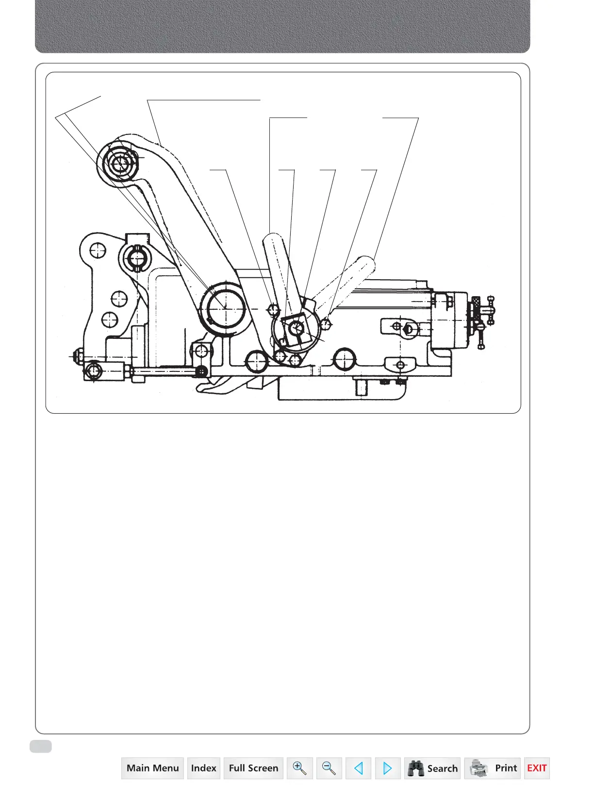
a) ADJUSTMENT OF POSITION CONTROL
LEVER
The adjustment is carried out in order to establish
the maximum raised position of the rockshaft's
lifting arms.
Completely lower the arms and apply a light
weight which creates a pressure in the cylinder
of 50- 60 bar.
Loosen the fastening screw (6) so as to free the
position control lever (1) from the shaft (5). With
the draft control lever (2) at its lowest position
against the backstop (E) raise the position control
lever (1) against the backstop (F).
LEVER 2LEVER 1
HYDRAULIC LIFTING ARM
AT END OF STROKE
10-5mm
F 6 5 E
 Loading...


