I-28
35 Series 4WD, Model - 3535, 4035, 4535 and 5035 SM June’08
Hydraulics
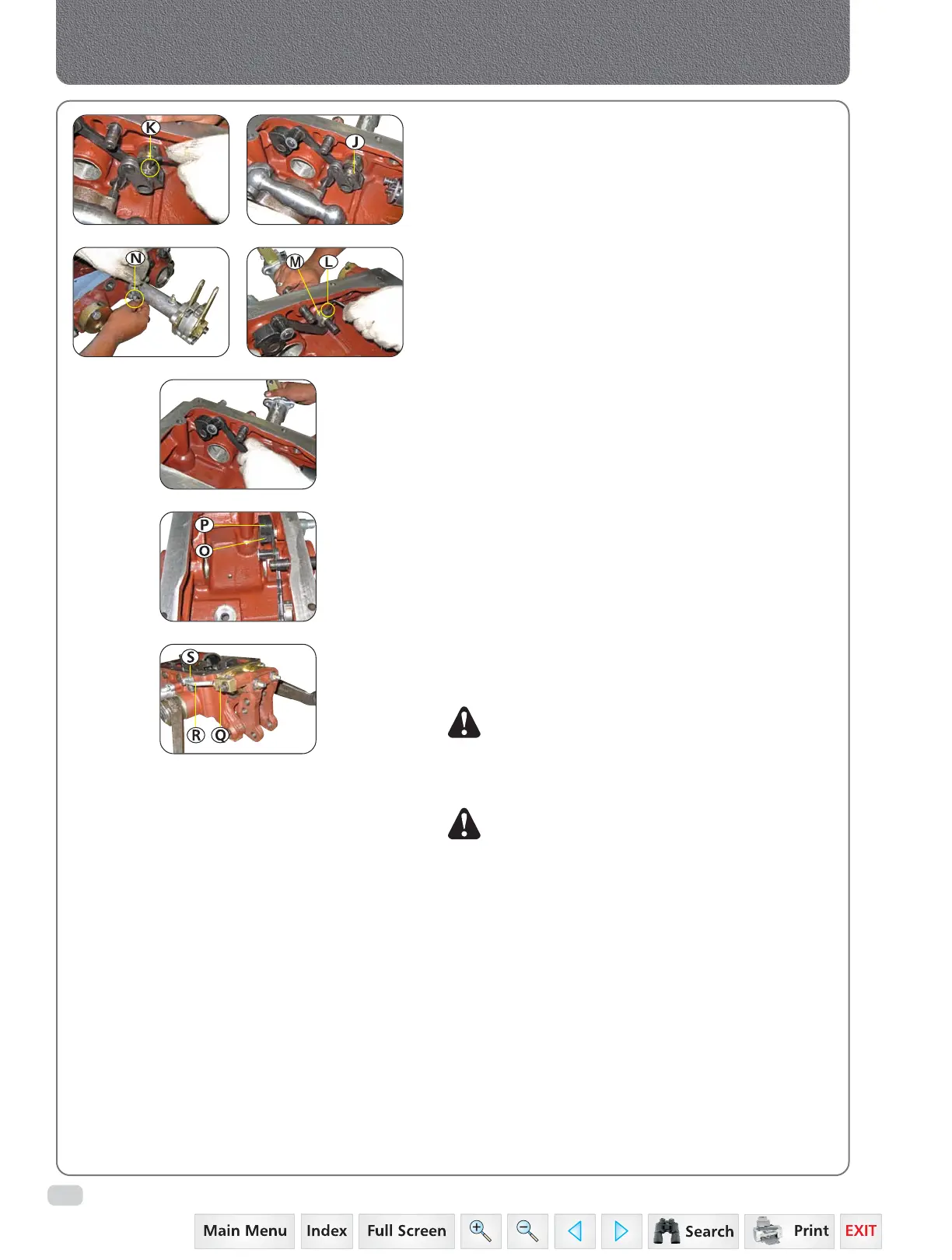
7. Remove cam (J) and allen set screws (k).
8. Loosen the allen set screw (L) of crank (M)
and remove control lever support assembly by
loosening bolts (N) and take out control lever
support assembly.
9. Remove roll pin (O) of cam (P) and snap ring.
10. Remove capscrew (Q) of tie rod (R) and pin
assembly (S).
NOTE: Inspect bushings for wear or damage.
Replace as necessary.
11. Reverse the dismantling procedure for assembly
and installation.
NOTE: Apply thread sealant to allen set screws
during assembly.
12. Adjust hydraulic lift unit position and draft
sensing feedback linkages.
 Loading...


