C-11
35 Series 4WD, Model - 3535, 4035, 4535 and 5035 SM June’08
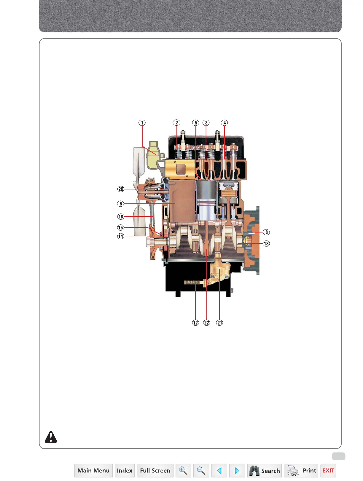
1) Thermostat, opens at 82
0
C (167
0
F) and allows
coolant to circulate. Not repairable, replace if
not functioning properly.
2) Valve Rocker arm shaft, diam. rocker arm
19 mm (¾”) drilled oil passage through valve
lever shaft center
bracket and valve
rocker arm shaft to
valve rocker arms.
3) Intake valve.
4) Valve guides, for
intake and exhaust
valves.
5) Exhaust valve.
6) Cylinder sleeves,
and pistons are
factory mated.
7) Cylinder sleeve
packing ring, replace
when removing
cylinder sleeves.
Thoroughly clean
grooves and apply
some soft soap or
soap solution when
installing new rings.
8) Flywheel, assembled with six bolts. When
flywheel reassembled retorque again.
9) Crankshaft rear oil seal, install carefully in
accordance with special instructions otherwise
oil leakage will result.
10) Crankshaft rear bearing, takes end thrust.
11) Flywheel ring gear, replaceable.
12) Floating screen for oil pump, before installing
thoroughly wash in gasoline.
13) Crankshaft, four bearings.
14) Crankshaft pinion, 33 teeth, when installing be
sure mark lines up with mark on
camshaft gear.
15) Crankshaft front
oil seal, when
installing apply a
mixture of heavy
oil and graphite
to the sealing
lip.
16) Camshaft drive
gear, 66 teeth,
removable.
17) Idler gear, when
installing be sure
that marks line
up with those
on crankshaft
gear and
injection pump
gear.
18) V-Belt, for
alternator pulley,
water pump
pulley & main
drive crank
pulley.
19) Injection pump drive gear, 66 teeth, adjustable
hub.
20) Water pump, fan belt driven, permanent
packings.
21) Oil pump, fitted on the crankcase with bolt.
22) Connecting rod, when installing apply engine
oil and see that the number mark at pump
side.
Cross Section of Engine (side view)
Introduction
NOTE: In overall Engine Section, 3 cylinder
pictures shown.
 Loading...


