C-14
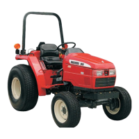
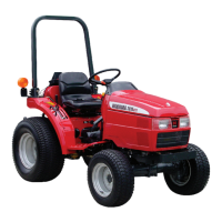
35 Series 4WD, Model - 3535, 4035, 4535 and 5035 SM June’08
Introduction
crankcase main oil gallery. A drilling carried
oil flow it to the idler drive gear on the front
of the engine to lubricate the gear bearing
and provide oil flow necessary to splash
lubricate the other gears, then drilling carry
oil to each camshaft bearing and crankshaft
bearing. The number two camshaft bearing
journal has a slot cut in it to provide metered
oil flow to the valve rocker arm shaft. When
the slot is aligned with the drilling from the
main oil gallery and the drilling to the valve
rocker arm shaft to metered amount of oil
is forced to the shaft. Each crankshaft main
journal is drilled to the rod journals and the
main bearing links have circumferential
grooves to provide continuous oil flow to each
rod bearing. The rods are designed with side
clearance to provide oil flow necessary to
splash lubricate the connecting rod small end
(wrist) pin bearing and the cylinder walls.
viii) Cooling System
Coolant is circulated through passages located
in the crankcase and the cylinder head, by a
centrifugal pump mounted in the front of the
crankcase. The drive for the water pump is
taken from the crankshaft by a belt and pulley
system. A thermostat situated in the water
outlet ensures that the coolant is not
circulated until it has reached the efficient
operating temperature.
For complete details refer service manual.
ix) Fuel System
The fuel system consists of fuel lines, fuel filter,
fuel injection pump, high pressure pipes, and
the fuel injection nozzles. The fuel injection
pump is controlled by a Mechanical Governor,
which governs the engine speed from idling
to full load. For complete detailed servicing
information on diesel fuel system components,
refer to the fuel injection system service
manual.
iv) Pistons
The Aluminium Alloy Pistons are cam ground
and are fitted with two compression rings and
one conformable oil control ring. The have
a cavity in the piston crown itself to make a
combustion chamber.
The fully floating piston pins are held in place
by Circlips at both ends.
Each piston is filled with two compression
rings made of cast iron. The top ring is chrome
plated. There is one oil control ring.
The purpose of oil control ring is to provide
an even circulation of lubricating oil giving
all over lubrication and cooling action for the
piston and sleeves. Excess oil is wiped down
to the sump by the lands of the ring.
v) Connecting rod
The I section connecting rods are forged steel
and carry a bronze bush at the small end for
installation of the piston pins. The big end
is mounted on the crankshaft over steel
backed alloy replaceable bearing inserts.
The big end bearing caps for each connecting
rod are matched fit and the matching parts
are numbered to ensure correct assembly.
vi) Flywheel is mounted on the rear of the
crankshaft secured by six bolts.
The replaceable ring gear is shrink fit on the
fly wheel.
vii) Lubrication System
Lubricating oils is stored in the engine oil pan
bolted to the bottom of the crankcase.
Oil is sucked through a fine mesh screen and
pick-up tube into the inlet of a 4 lobe internal
gear pump. The pump is driven by a gear on
the camshaft. The pump has a build in relief
valve to limit maximum pressure. Oil is forced
from the pump through the filter into the
engine lubrication passages. The filter has a
bypass valve designed to prevent loss of
lubricating oil flow if the filter becomes
stagged. Oil from the filter enters the
 Loading...
