C-27
35 Series 4WD, Model - 3535, 4035, 4535 and 5035 SM June’08
If the running clearance between valve and
valve guide exceeds 0.2 mm (0.008 in) the
valve guide should be replaced.
e. Inspect the cylinder head and crank case for
warpage if engine has been run with a
blown head gasket.
4d. BEFORE REWORK
NOTE:
Check whether the cylinder height permits
reworking.
Check to see if nozzle tip protrusion will retain
within specified limits after rework.
(Nozzle protrusion of 2.3/1.8 mm/0.90”/0.70” is
to be ensured)
To remove valves compress valve springs with
compressor tool and take out spring retainer locks.
Fig. 9.
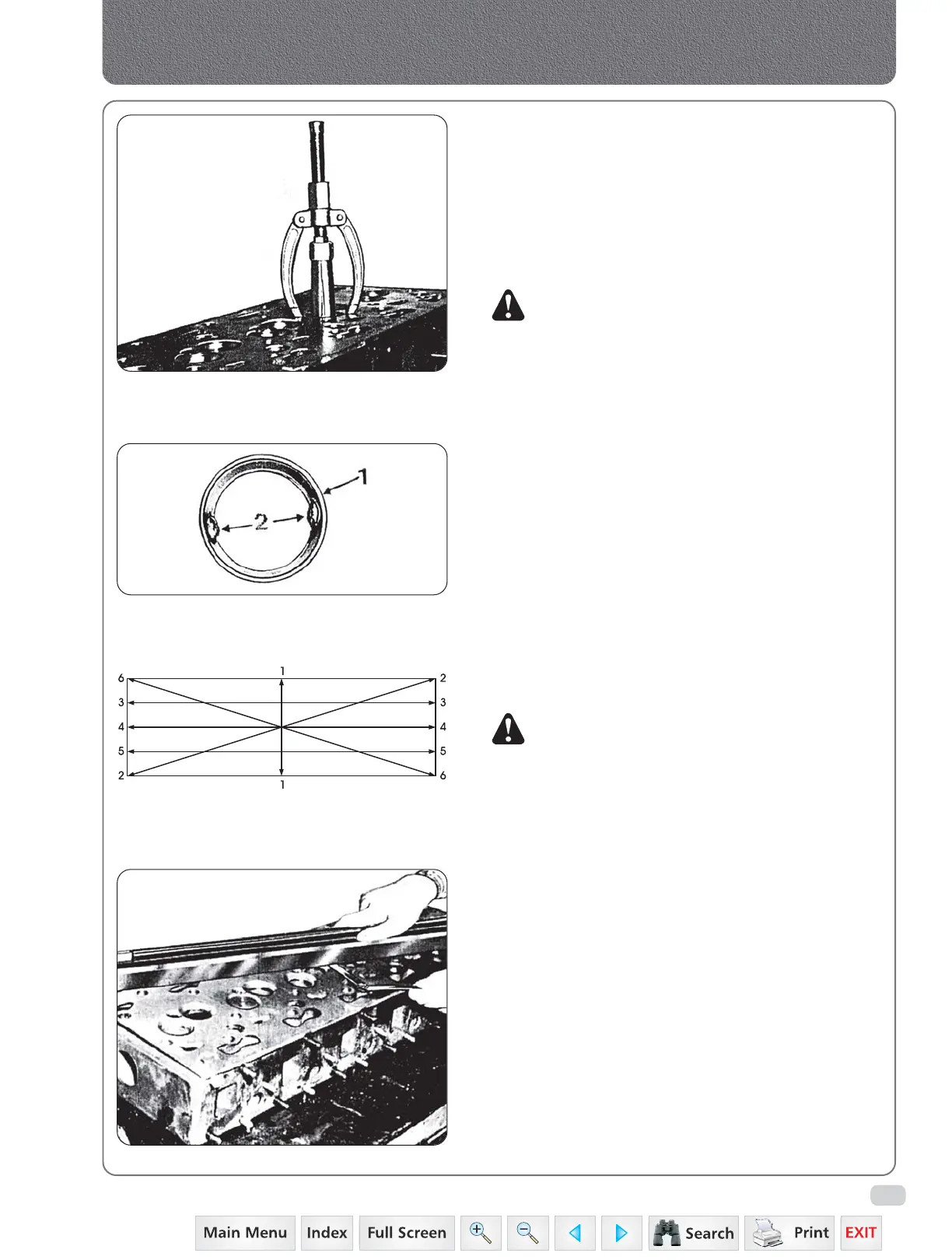
To remove valve seat inserts, first weld two
opposite lugs (2) Fig. 11 to provide puller grip.
4e. CLEANING, INSPECTION AND REPAIR
Clean the cylinder head thoroughly.
Remove carbon deposits from the bottom of the
cylinder head and out of exhaust valve ports.
Flush out the water jacket to remove scale and
dirt.
NOTE: Make sure water passages are free of
obstructions, rust or scale.
Inspect the cylinder head (and the crankcase) for
warpage if engine has been run with a blown head
gasket. Fig. 13.
Observe checking pattern, fig. 12 see “Specification”.
f) Check the valve stems for bends, wear, pitting or
mushrooming of the ends. Check the collet
grooves in the stems to ensure they have not lost
their shoulders.
g) Check that the valve heads are not excessively
worn or pitted.
h) Check the valve springs for rust, pitting or cracks
and against the loads given in specification.
i) Check the retainers for rust and cracks.
j) Check and replace valve seals.
k) Check the outside face and the ribs inside the
collects for wear. It is advisable to always use new
collets.
Fig. 10
Removing valve seat inserts
Fig. 11
1. Exhaust valve seat insert 2. Welded lugs
Fig. 12
Checking pattern, cylinder head and crankcase
Fig. 13
Manifolds, Cylinder Head & Valves
 Loading...


