C-38
35 Series 4WD, Model - 3535, 4035, 4535 and 5035 SM June’08
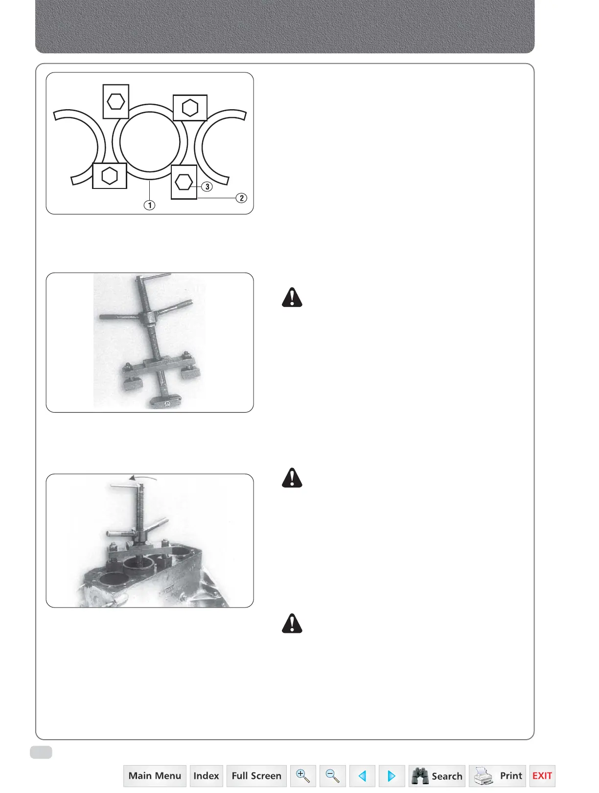
MST-H1-EN-1 (fig.13) as follows :
• Insert the sleeve puller from the top of the
crankcase (fig.14).
• Fix the thrust plate sides at lower portion
of cylinder sleeve. The bigger side of thrust
plate is suitable for DI Engine.
• Position the bracket on top of the crankcase
and tighten the nut over the bracket of puller
bar, by rotating handle, the sleeve will be
pulled out while tightening the nut.
c) Before installing sleeve, check the counter bore
at top and sealing ring groove at the bottom are
clean and free from foreign material. All sleeves
should enter crankcase bores full depth and should
free to rotate by hand (without sealing ring).
NOTE: The cylinder head gasket forms the upper
cylinder sleeve seal, and excessive sleeve stand
out will result in coolant leakage. To test lower
sealing rings for proper installation, fill crank
case water jacket with cold water and check
for leaks near bottom of sleeves.
d) Check the sleeves for scoring or signs of corrosion.
3. INSTALLATION
a) Dip each cylinder sleeve packing ring in a soap
solution and install it in the groove in the
crankcase bore.
b) Coat bottom of each sleeve with soap solution
and press the sleeve into the crankcase bore.
NOTE: Weights refer to complete connecting rods with
bushing, bearing cap and bolts but less
securing wire and without bearing halves.
c) Check from below to ensure that the packing rings
have not been sheared or pushed out of position.
d) Check the cylinder sleeve protrusion (Fig.11) to
specifications. The top face of the sleeve can be
0.05 mm above the cylinder block face or 0.03 mm
below the cylinder block face. To ensure the above
dimension, the cylinder sleeve and the cylinder
block should be matched.
NOTE: Check cylinder sleeve protrusion according to
checking sleeve protrusion procedure given
below :
e) Install the piston assemblies.
1. Place the sleeve in the crankcase with out
‘O’ Ring.
2. Clamp the sleeve down using four holding
adapters/plate shown in fig.12 place sleeve
holding plate locally.
Fig. 12
1. Sleeve 2. Holding plate 3. Bolt
Fig. 13
Fig. 14
Connecting Rods, Pistons & Cylinder Sleeves
Image is representative
 Loading...


