C-22
35 Series 4WD, Model - 3535, 4035, 4535 and 5035 SM June’08
2b. INSTALLATION :
a) Reverse the removal procedure.
b) It is always advisable to replace the Inlet & exhaust
manifold gaskets with new ones.
c) Torque the mounting bolts at the specified torque
to avoid leakage of gases.
2c. CLEANING, INSPECTION & REPAIR
Clean the manifold and inspect for cracks and distortion.
Replace the manifold with New one, whenever distortion
is more than 0.4 mm (.016 in) per 250mm (10 inch)
length. Inspect Air Hose & Clamps. Inspect retainer bolts
and their washers, replace damage parts.
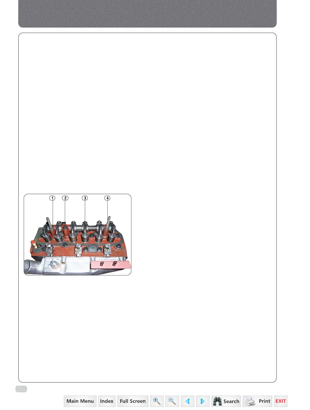
3. VALVE ROCKER ARM SHAFT ASSEMBLY
3a. REMOVAL :
Thoroughly clean the engine externally.
a) Remove the radiator brace, clamps/stiffener and
rubber washer. Then remove the valve housing
cover and the gasket.
b) Remove the PCV.
c) Remove the two nut (1-3) from studs (4-3) from
the outer valve lever shaft bracket. Which hold
the valve lever shaft brackets cylinder head.
d) Remove the bolt (2-3) from the centre (long valve
lever bracket.
e) Lift of the valve rocker arm shaft and brackets.
f) Lift out the push rods marking them so that they
may be returned to their original positions.
3b. DISMANTLING :
Rocker Arm shaft
a) Remove circlip from both ends of the shaft
and take out Rocker Arms and other parts
(10 to 25-7).
b) To shift from centre bracket remove the roll pin
and remove the shaft. Identify the rocker arms
so that the can be installed in their original
position.
3c. INSPECTION & REPAIRS
a) Thoroughly clean all components in Kerosene or
Diesel and blow using compressed air.
Be sure all oil passages are free from sludge and
sediment.
b) Check the valve lever shaft expansion plugs.
c) Check the clearance between the valve rocker arm
shaft and valve rocker arm bushings.
Manifolds, Cylinder Head & Valves
Fig. 3
 Loading...