C-23
35 Series 4WD, Model - 3535, 4035, 4535 and 5035 SM June’08
d) Check the valve lever bracket for wear in the bore.
e) Replace valve rocker arms that show excessive
wear of hammering at the ends (2-3) which
contact the valve, remove only enough material
to give an even face on the end of the valve lever
and take care that the rounding is maintained
lengthwise to ensure perfect grinding action on
valve stem.
NOTE: Replace worn screw & nut with new ones.
f) Check expansion plugs on both ends of the lever
shaft for leakage and replace plugs, if necessary,
using sealer.
g) Check valve lever springs against specifications and
replace with new ones if signs of corrosion chafing
or fatigue show.
3d. ASSEMBLY :
Engine valve rocker arm (Ref. Fig .7).
a) Position the shaft in the center bracket ensuring
that the oil hole in the shaft is towards the bottom
of the bracket. Secure it with a new groove pin.
b) Assemble rocker arm spacer, rocker arm, spring
rocker arm bracket, rocker arm to the shaft and
secure them with a washer and retaining ring.
3e. INSTALLATION :
a) Loosen the lock nuts on each valve lever and back
off the adjusting screws.
b) Install the value rocker arm shaft assembly on the
studs as shown in Fig. 7 and install the nuts
(1-3) finger tight.
c) Install the bolt in the centre bracket then tighten
the nuts to the correct torque.
d) Adjust the valve clearance as detailed in para
“ADJUSTMENTS”.
e) Install the valve housing cover using a new gasket
and rubber washers.
f) Install the nuts over the clamps/stiffener (over valve
housing). Then tighten them to the specified
torque.
3f. ADJUSTMENTS :
a) Tappet clearance must be set after the cylinder
head cap screws have been tightened to the
correct torque.
b) Move each piston in the firing order to top dead
center on the compression stroke. This can be
ascertained by watching the valves of No.4 cylinder
until intake valve just beginning to open and
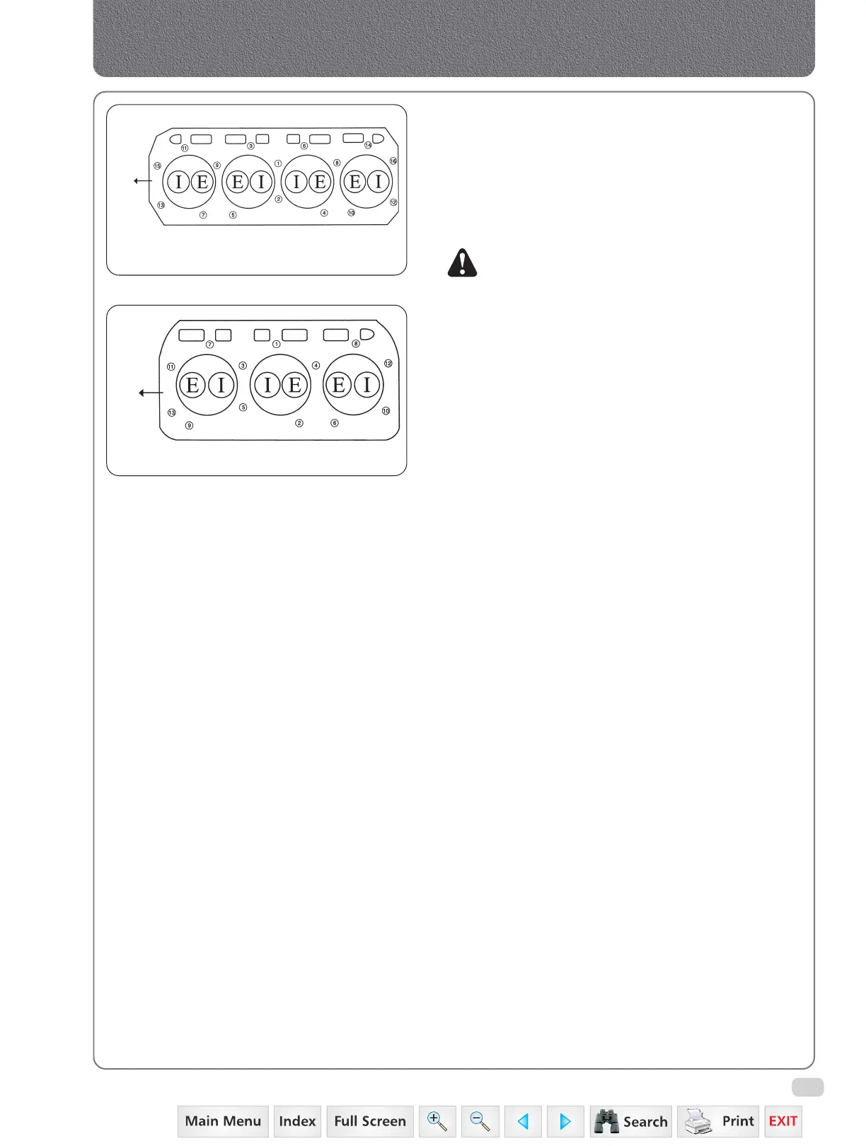
Manifolds, Cylinder Head & Valves
Fig. 4
Tightening sequence for 4 Cylinder Engines
FRONT
SIDE
Fig. 4
Tightening sequence for 3 Cylinder Engines
FRONT
SIDE
 Loading...