Do you have a question about the Mahr Millimar S 1840 and is the answer not in the manual?
For connecting one or two inductive probes.
For connecting pneumatic measuring equipment.
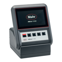
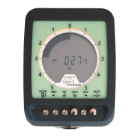
Details the front panel layout, including light bars, display, and keypad.
Describes the rear panel connections for power, interfaces, and probes.
Procedure to change the instrument's display language from the available options.
Adjusts the brightness level of the analog light bar display for optimal visibility.
Configures the display unit (mm, µm, inch) for measuring values.
Defines the numerical display format and resolution for measuring values.
Specifies whether one or two features are displayed simultaneously.
Adjusts the scaling and gradation of the analog light bar display range.
Sets the origin point (CENTER, BOTTOM, TOP) for the light bar display range.
Programmable feature to assign up to six functions for quick access via the MENU key.
Procedure to calibrate the zero point and indication values for a measuring channel.
Adjusts the sensitivity of probe C2 relative to probe C1 for instruments with inductive probes.
Enters a factor other than 1 for linking formulas to correct displayed feature values.
Defines the formula for calculating a feature, combining factors and channel inputs.
Compares a single master contact value to a nominal value for correction.
Uses two masters to correct probe values and adjust characteristic curve pitch.
Procedure to select between one-point (MAST 1P) or two-point (MAST 2P) master measurement.
Inputting the master workpiece's actual dimension for one-point master measurements.
Steps to perform a one-point master measurement and display deviation.
Inputting nominal values for the larger and smaller masters for two-point master measurements.
Steps to perform a two-point master measurement, comparing two masters.
Checks the validity of subsequent master measurements against the original.
Defines the maximum and minimum dimensions a workpiece can have to function correctly.
Sets warning limits before tolerance limits to recognize trends and prevent issues.
Configures the light bar colors to indicate compliance or exceeding of warning/tolerance limits.
Restricts the validity range of measuring values to prevent results beyond the measuring range.
Filters probe signals to avoid disturbances by setting cutoff frequencies in preset steps.
Selects the measuring mode (NORMAL or AUTOMAT) for workpiece measurements.
Continuous measurement mode; START saves value and initiates new measurement.
Automatic measurement mode; START initiates, START again ends measurement or pause.
Sets a delay between pressing START and the actual measurement start.
Procedure to set a seven-digit password to protect catalog functions and parameters.
Measures the thickness of a workpiece by summing probe values.
Measures the height of a step on a workpiece using probe value differences.
Measures radial runout and eccentricity of a workpiece relative to centering tips.
Specifies the communication method (e.g., ASCII, OPTORSS) for data exchange.
Defines data bits, stop bits, and parity check for data transfer.
Sets the data transfer speed (baud rate) required for communication.
Configures control signals for data flow control via hardware or software handshake.
Determines if data transfer is manual, automatic, or continuous.
Recommended settings for connecting to Mahr MSP2 or other ASCII printers.
Recommended settings for computer data transfer using various protocols.
Details commands for querying data and changing settings using the OPTORSD protocol.
Describes commands for data requests, settings changes, and measurement control.
Explains how to request current measuring values using the OPTORSS protocol.
Protocol used by the D 1000 S configuration program for data and settings transmission.
Describes modes for assigning functions to digital control outputs for external signals.
Explains how to assign functions to digital control inputs via Millimar or D1000S.
Illustrates practical applications for digital control inputs and outputs with diagrams.
Details the analog output for connecting recorders or instruments with analog inputs.
Configures which feature (light bar, line 1, line 2) is output via the analog signal.
Adjusts the sensitivity of the analog output voltage based on the displayed feature.
| Brand | Mahr |
|---|---|
| Model | Millimar S 1840 |
| Category | Measuring Instruments |
| Language | English |