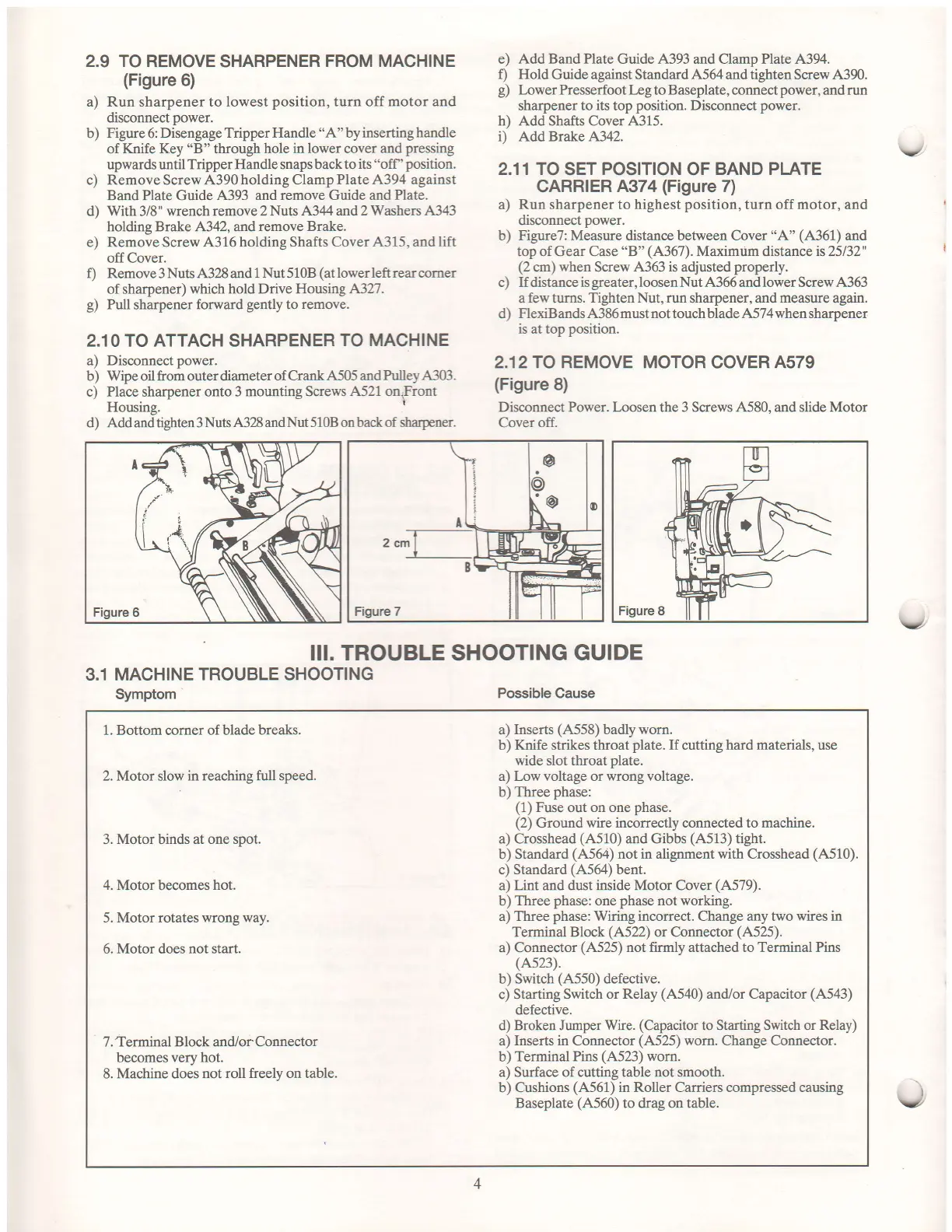
2.9 TO REMOVE
SHARPENER
FROM MACHINE
(Figure
6)
a) Run sharpener to lowest
position,
turn off motor and
disconnect
power.
b)
Figure
6: Disengage
Tripper Handle
"A"
by
inserting handle
of
Knife Key
"B"
through
hole in
lower
cover
and
pressing
upwards until
Tripper Handle snaps back to
its "off
'
position.
c) RemoveScrew.4'390holdingClampPlate,4'394
against
Band Plate Guide
,4393 and remove Guide and
Plate.
d) With 3/8" wrench remove 2
Nuts ,4.344 and 2 Washers ,4'343
holding Brake 4342, andremove
Brake.
e) RemoveScrew
,{316 holding Shafts Cover
4315,
and
lift
offCover.
f) Remove 3 Nuts 4'328 and 1
Nut
5
10B
(at
lower left rear corner
of sharpener)
which hold Drive Housing 4327.
g)
Pull
sharpener
forward
gently
to
remove.
2.10 TO
ATTACH
SHARPENER
TO MACHINE
a) Disconnect
power.
b) Wipe oil from outer diameter
of CrankA5O5 andPulleyA303.
c)
Place
sharpener
onto 3 mounting Screws
,4'521 on,Front
Housing.
I
d) Add and tighten 3
Nuts ,{328 and Nut 5108 on back of Sarpener.
III. TROUBLE SHOOTING
GUIDE
3.1 MACHINE
TROUBLE SHOOTING
Symptom
Possible Cause
e)
Add Band Plate
Guide A393 and Clamp Plate 4'394.
f) Hold
Guide against Standard
,4.564
and tighten Screw 4390.
g)
Lower Presserfoot Leg to Baseplate, connect
power,
and
run
sharpener to
its
top
position.
Disconnect
power.
h) Add Shafts Cover 4315.
i) Add Brake A342.
2.11 TO
SET
POSITION
OF
BAND PLATE
CARRIER
4374
(Figure
7)
a) Run sharpener to
highest
position,
turn off
motor,
and
disconnect
power.
b) Figure7: Measure distance between Cover
"A"
(A361)
and
top of Gear Case
"B"
(4367).
Maximum
distance
is25132"
(2
cm)
when
Screw
4'363 is
adjusted
properly.
c) If distance is
greater,
loosen Nut .4'366 and lower Screw A363
a
few
turns.
Tighten Nut, run
sharpener, and
measure
again.
d)
FlexiBands ,4'386 must not touch blade ,4'574 when sharpener
is at top
position.
2.12TO REMOVE MOTOR COVER A579
(Figure
8)
Disconnect Power. Loosen the 3 Screws A,580, and slide Motor
Cover off.
v
v
1. Bottom comer of blade
breaks.
2. Motor
slow
in reaching ftrll speed.
3.
Motor binds at one spot.
4.
Motor becomes
hot.
5. Motor rotates
wrong way.
6. Motor does
not start.
7. Terminal Block and/or Connector
becomes very hot.
8. Machine does
not roll freely on table.
a)
Inserts
(,4'558)
badly worn.
b) Ifuife strikes throat
plate.
If
cutting
hard materials,
use
wide slot throat
plate.
a) Low voltage or wrong voltage.
b) Three
phase:
(1)
Fuse
out
on one
phase.
(2)
Ground
wire incorrectly connected to machine.
a) Crosshead
(4'510)
and Gibbs
(A513)
tight.
b) Standard
(4'564)
not in alignment with Crosshead
(,{510).
c)
Standard
(,4'564)
bent.
a) Lint and dust inside Motor Cover
(A579).
b)
Three
phase:
one
phase
not working.
a)
Three
phase:
Wiring incorrect. Change any two
wires
in
Terminal Block
(A522)
or Connector
(A525).
a) Connector
(4.525)
not firmly attached to Terminal Pins
(4523\.
b) Switch
(,4,550)
defective.
c) Starting Switch or
Relay
(4'540)
and/or Capacitor
(4'543)
defective.
d) Broken Jumper Wire.
(Capacitor
to Starting Switch or
Relay)
a)
Inserts in Connector
(A525)
worn. Change Connector.
b)
Terminal Pins
(4523)
wom.
a) Surface of cutting table not smooth.
b) Cushions
(4'561)
in Roller Carriers compressed causing
Baseplate
(4'560)
to drag on table.
4
I
 Loading...