Do you have a question about the Major tech MT474 and is the answer not in the manual?
Overview of international symbols used to indicate potential dangers and warnings.
Important general guidelines and precautions for safe operation and handling.
Critical safety warnings regarding voltage limits, probe handling, and instrument condition.
Procedure to verify the voltage tester's functionality before use.
How to perform standard voltage measurements using the tester's LEDs and sound.
Using the tester with reduced internal resistance for specific voltage tests.
Method for identifying a phase conductor using a single probe.
Performing voltage tests in RCD-protected circuits to avoid false tripping.
Procedure for testing continuity and diodes with audible and visual indicators.
How to determine the phase sequence (rotary field) in a three-phase system.
Using the integrated light for better visibility in low-light conditions.
General guidelines for maintaining the voltage tester for optimal performance.
Instructions for cleaning the instrument safely and effectively.
Recommendation for periodic calibration to ensure measurement accuracy.
Steps for replacing the batteries when no audible signal is detected.
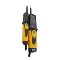
The Major Tech MT474 is a 690V Voltage Tester designed for electrical professionals to safely and accurately test voltage in various electrical systems. This instruction manual provides comprehensive guidance on its operation, safety warnings, and maintenance, ensuring reliable performance and user safety.
The MT474 is a versatile voltage tester capable of performing several critical electrical tests. Its primary function is voltage testing, which automatically activates when connected to a power source exceeding 6V. The voltage is displayed via LEDs, with distinct indications for AC and DC voltages. For AC voltages, both "+" and "-" LEDs illuminate, accompanied by an audible signal. For negative DC voltages, the " " and "-" LEDs illuminate, also with an audible signal. The device features an LED row indicating voltage steps at ±12, 24, 36, 50, 120, 230, 400, and 690V AC/DC. It's important to note that for DC voltages between approximately 0V and -/+4.5V, automatic switch-on may not occur due to technical reasons.
The tester also includes a low impedance test function. Without pressing the low impedance buttons, the device indicates voltage steps from ±24V to 690V AC/DC. By pressing both low impedance push buttons, the tester switches to a lower internal resistance, which helps suppress inductive and capacitive voltages. This activates the low impedance indication. The duration of this load test depends on the measured voltage, and the device is equipped with thermal protection to prevent excessive warming.
A single-pole phase test is another key feature, operational only with installed and good condition batteries. This test starts at an AC voltage of approximately 100V (pole >100V AC). It helps identify external conductors, with a signal sound and the illumination of an LED (5) indicating the phase. However, it's crucial to understand that the single-pole phase test is not suitable for definitively determining if a line is live; for that, a double-pole voltage test is always required. The display function during single-pole phase tests may be impaired under certain conditions, such as when using insulating body protective equipment.
The MT474 also supports voltage testing with RCD trip test. In systems equipped with RCD circuit breakers, the tester can trip an RCD switch at a nominal residual current of 10mA or 30mA by measuring the voltage between L and PE. To avoid unintended RCD tripping, it is recommended to first test between L and N for approximately 5 seconds, then proceed with testing between L and PE.
Continuity test/diode test is available, provided batteries are installed and in good condition. A signal sound and the illumination of the continuity LED (8) indicate continuity.
A unique feature is the rotary field indication, which is always active and displays "R" or "L" symbols. This function helps determine the rotary direction within a three-phase system by indicating the voltage between two external conductors. Connecting the instrument test probe to the supposed phase L2 and the handle test probe to the supposed phase L1 will display the voltage and rotary field direction. "R" signifies that the supposed phase L1 is the actual L1 and L2 is the actual L2, while "L" indicates that the supposed phase L1 is the actual L2 and L2 is the actual L1. Re-testing with exchanged test probes should illuminate the opposite symbol.
Finally, the MT474 includes a measurement point illumination feature, activated by pressing a button on the instrument's rear. This illuminates the measurement point, making it easier to work in poorly lit conditions, such as inside division switch cabinets.
The MT474 is designed with user safety and convenience in mind. It incorporates International Safety Symbols such as a warning for potential danger, caution for dangerous voltage (risk of electrical shock), and double insulation. Users are advised to always comply with the instruction manual and use utmost attention during operation. It is critical not to exceed the maximum allowable input range for any function and to use insulated personnel body protective equipment up to 690V.
The device features a function test / self-test capability. When test probes are connected, an acoustic sound should be audible, and the continuity LED (8) should illuminate, confirming basic functionality. The voltage display works even with discharged or no batteries, but other functions like single-pole phase test and continuity test require good batteries. The instrument is equipped with an internal load that can trip RCD protection devices of 10mA or 30mA, a feature to be used cautiously as described above.
The MT474 is designed for use within low voltage systems up to 690V. It is crucial to ensure the test leads and instrument are in perfect condition before any measurement. When using the instrument, only the handles of the probes should be touched, never the probe tips. The instrument should not be used under damp conditions. Optimal display performance is guaranteed within a temperature range of -10°C to +55°C and relative humidity below 85%. If the operator's safety cannot be guaranteed due to obvious damage, incorrect measurements, prolonged storage under unfavorable conditions, or mechanical stress during transport, the instrument must be removed from service.
The instrument should only be used for its designed purposes, adhering to safety references, technical data, environmental conditions, and usage in dry environments. Any modification or change to the instrument will void its operational safety, and it should only be opened by an authorized service technician for repairs.
The MT474 requires minimal maintenance when used in compliance with the instruction manual. In case of functional errors during normal operation, the service department should be contacted for inspection.
For cleaning, it is essential to remove the voltage tester from all measurement circuits first. If the instrument becomes dirty from daily use, it can be cleaned with a damp cloth and a mild household detergent. Acid detergents or dissolvents should never be used. After cleaning, the voltage tester should not be used for approximately 5 hours.
Calibration is recommended periodically to ensure the specified accuracy of measurement results. Major Tech suggests a calibration interval of one year, to be performed by their service department.
Battery replacement is necessary if no signal sound is audible when short-circuiting the test probes. To replace batteries, completely disconnect the voltage tester from the measurement circuit. Remove the discharged screw, battery cover, and old batteries. Replace them with two new "AAA" (UM4 R03) batteries, ensuring correct polarity. Finally, close the battery cover and re-screw the screw.
| Model | MT474 |
|---|---|
| Display | LCD |
| Diode Test | Yes |
| Continuity Test | Yes |
| Auto Power Off | Yes |
| Type | Digital |
| Current Range | 10A |
| Capacitance Range | 0.1nF to 100μF |
| Frequency Range | 10MHz |
| Temperature Range | 1000°C |
| Safety Rating | CAT III 600V |