9
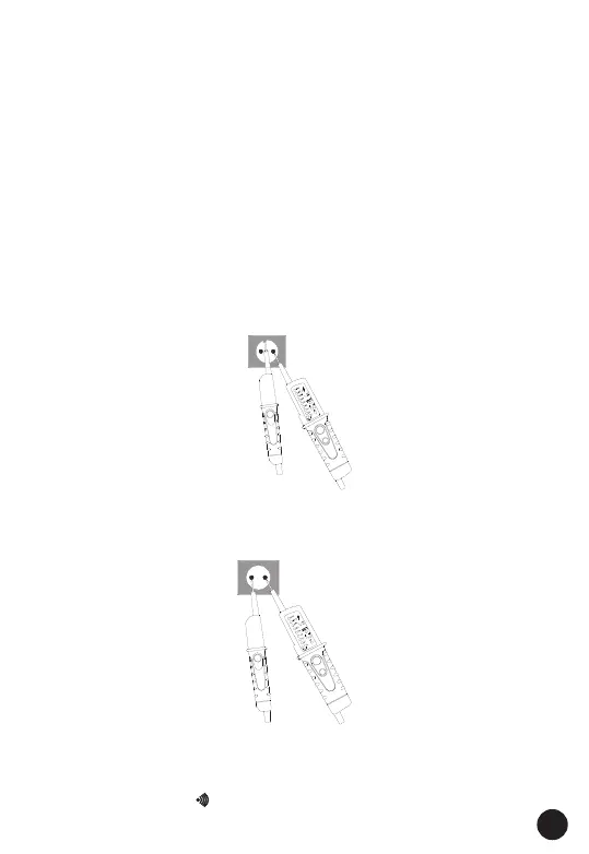
Ÿ The single-pole phase test starts at an AC voltage of approx. 100V (pole
>100V AC).
Ÿ When using single-pole phase tests to determine external conductors
the display function may be impaired under certain conditions (e.g. for
insulating body protective equipment on insulation locations).
Ÿ The single-pole phase testing is not appropriate to determine whether a
line is live or not. For this purpose, the double-pole voltage test is
always required.
Ÿ Connect both test probes with power source.
Ÿ A signal sound indicates the phase.
Ÿ The LED (5) is illuminated in the display.
5.5. Voltage Test with RCD Trip Test
During voltage tests in systems equipped with RCD circuit breakers, a
RCD switch can be tripped at a nominal residual current of 10mA or 30mA
by measuring the voltage between L and PE.
To avoid RCD tripping a test has to be carried out between L and N during
approx. 5s. Immediately afterwards, voltage testing between L and PE
can be carried out without RCD tripping.
5.6. Continuity Test / Diode Test
The continuity test /diode test is only possible when batteries are installed
and in good condition. A signal sound is audible for continuity and the
LED for continuity LED (8) is illuminated.