7
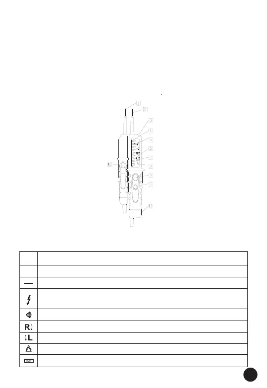
3. VOLTAGE TESTER DESCRIPTION
1 - Handle test probe - (L1)
2 - lnstrument test probe + (L2)
3 - Measurement point illumination
4 - LEDs for voltage display
5 - LED for single-pole phase test
6 - LED for low impedance test
7 - LED for left/right rotary field
8 - LED for continuity
9 - Low impedance switch (L2)
10 - Measurement point lighting
Button
11 - Battery case
12 - Low impedance switch (L1)
4. EXPLANATION OF SYMBOLS
DC voltage
AC voltage
DC voltage negative potential (DC)
Phase display from 100 to 690V - 50/60Hz when used as a
"single-pole" phase tester.
Continuity test symbol
Rotating field display clockwise
Rotating field display anticlockwise
Device for work to be performed with voltage present
Battery replacement symbol
DC
AC
The voltage tester shows the following symbols: