Piston
Maintenance / Reassembly
A5.05. 02.10.01.01
M20
en / 30.09.2010 IB004785 2/3
02
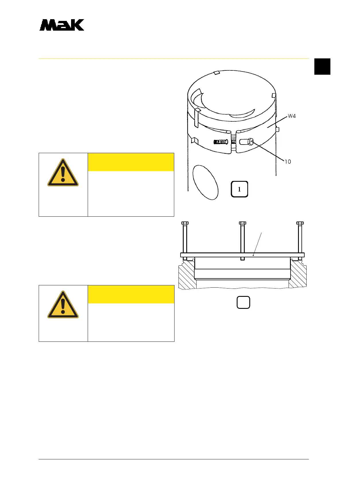
3. Slacken the tightening screw (fig. 1/10)
until the piston insertion device (W4) has
been relieved and can be guided freely
over the piston rings.
4. Apply Molykote paste "G-Rapid Plus" to
the thread and contact surface of the
tightening screw (10).
5. Place the piston insertion device (W4)
over the piston ring zone and tighten the
tightening screw (10).
6. Check the floating position of the rings by
turning the piston insertion device (W4).
7. Mount the piston assembly ring (fig. 2/
W3).
8. Mount the piston mounting/extraction
device (fig. 3/W1).
9. Attach the piston (3) to the crane and raise it.
10. Carefully insert the bottom end in the cylinder liner with the cylinder number mark towards the
control side and lower the piston exactly in the cylinder axis so that the bottom end does
not jam in the cylinder liner.
11. Let the piston insertion device (fig. 1/W4) lie flush on the piston assembly ring (fig. 2/W3) and ca-
refully lower the piston further guiding the bottom end over the crank pin by hand.
CAUTION
Make sure the piston rings do
not sit on the outer edge of the
ring groove when tightening the
tightening screw. Eliminate any
faulty gripping by tapping the
piston insertion device slightly.
CAUTION
Turn the crank pin to a favou-
rable installation position. The
bottom end must not knock
against the crank pin when
being lowered.