Camshaft
Repair / Disassembly and reassembly
A5.05. 04.04.01.00
M20
en / 31.05.2010 IB001455 3/3
04
2. Assembly
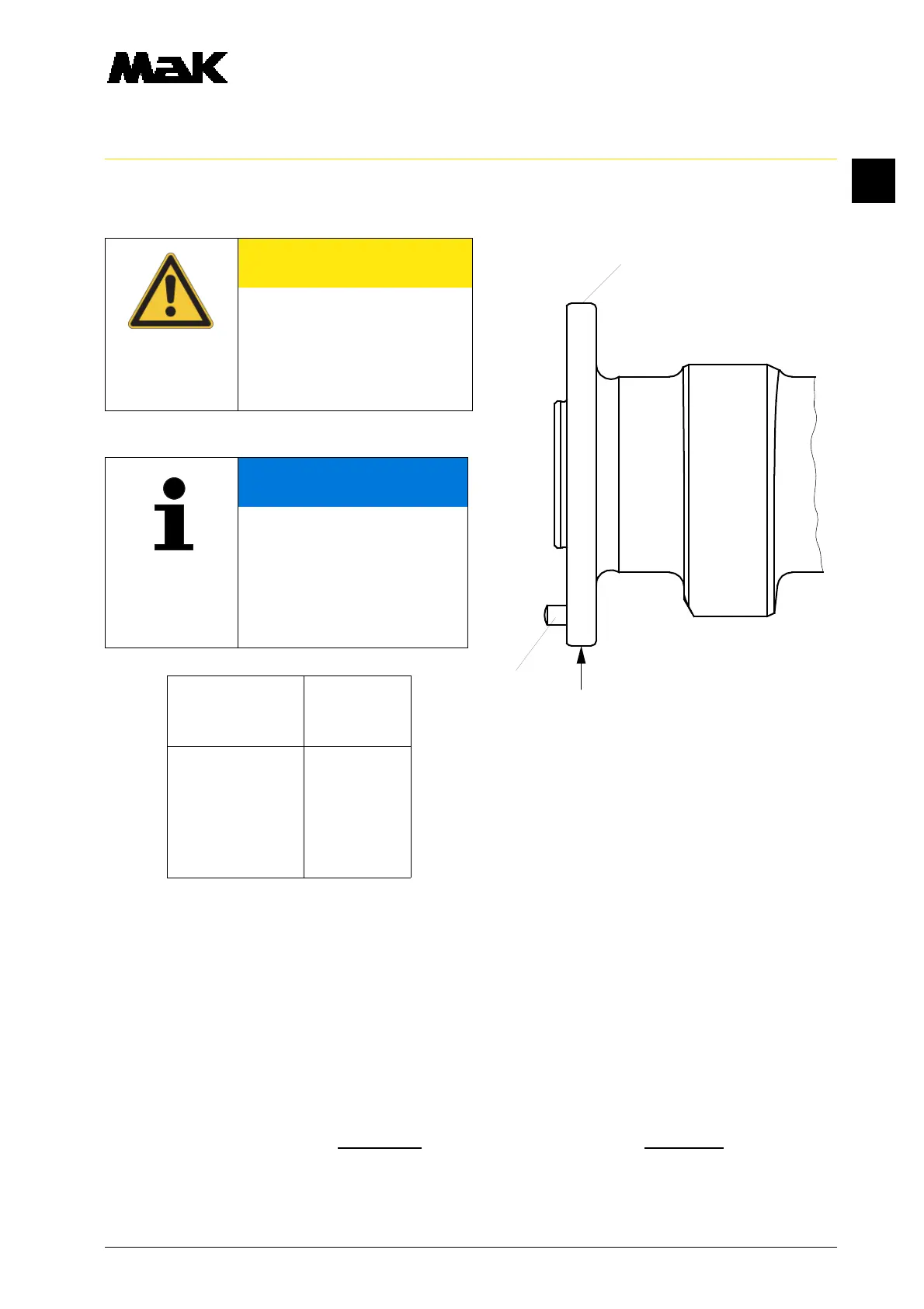
Camshaft Flange
piece index
cylinder No.
1 4
2 2
3 3
4 4
5 5
6 6
2.1 Position the camshaft pieces in reverse disassembly order.
2.2 Grease the threads and contact surfaces of the flange screws with Molykote paste
”G-Rapid Plus” and bolt the loosened camshaft pieces.
2.3 Tighten the flange screws crosswise with a torque of
100 Nm = 50°
°°
° angle of rotation.
Remove the camshaft - mounting devices (W1).
2.4 Remove the locking screws (W2) of the raised valve and pump drive rocker.
2.5 Mount the valve rocker (01.02.01.nn) and check the valve clearance (01.01.01.nn).
2.6 Check the lubricating oil flow.
CAUTION
Do not cant camshaft piece in
the camshaft bearings during
removal.
Handle with utmost caution.
Danger of destruction of the
bearings.
NOTE
The camshaft flange (Fig. 4/
31) of every piece is pinned
according to the cylinder and
position in accordance with the
firing order (32) and provided
with a flange index (33) (see
table).