Injection Pump
Maintenance / Disassembly and reassembly
A5.05. 07.03.01.03
15000, 7500
M20
en / 31.05.2010 IB024918 3/4
07
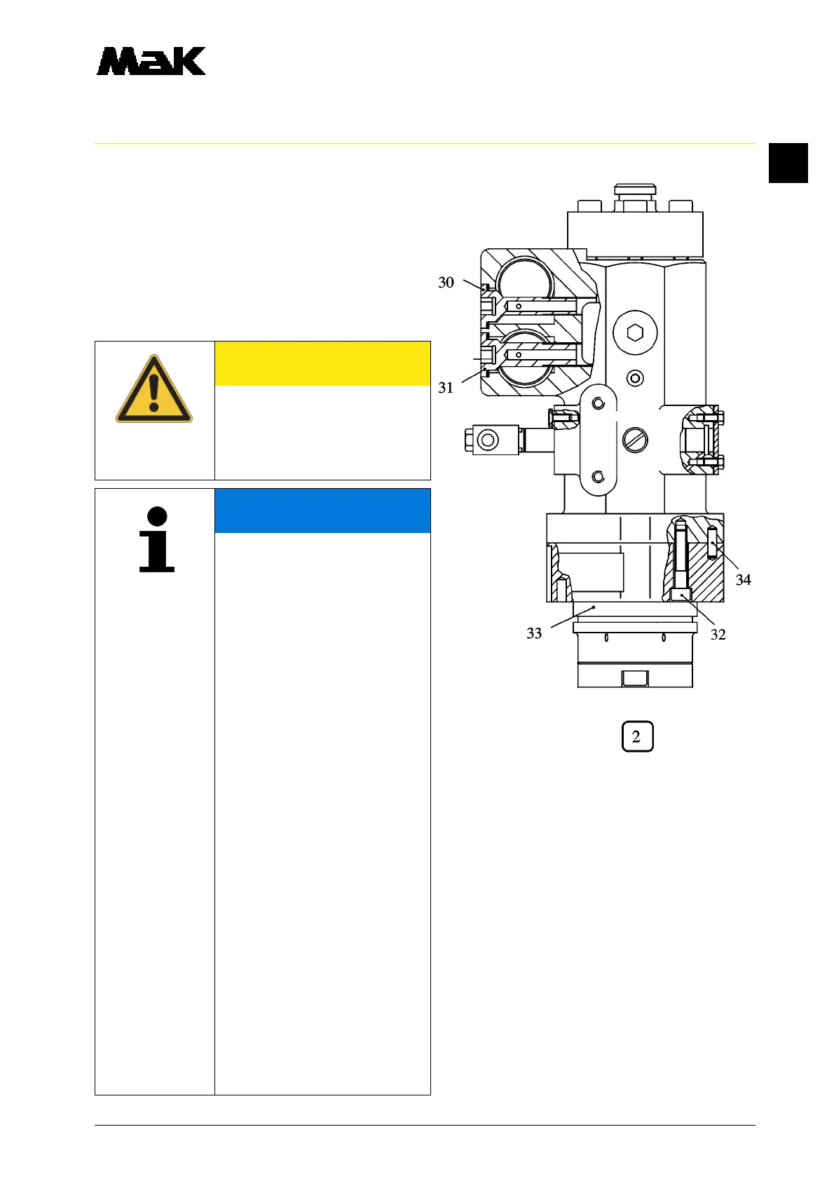
1.10 Dismantle the fuel outlet throttle screw
(Fig.2/30) and the fuel inlet throttle screw
(31).
1.11 Clean all parts with gas oil and
a hard brush and blow through with
compressed air. Check lube oil bores
for free passage.
1.12 Renew all O-rings and sealing rings.
CAUTION
If a possibly existing throttle (25)
is to be exchanged, it has to be
replaced, together with the
connector, by the throttle-
connector (26).
NOTE
Insert O-rings with vaseline unt-
wisted into slots, do not pull
across sharp edges of
the components.
During visual inspection pay
special attention to the following
wear phenomena:
•
plunger, scores marks on the
running surface. Control helix
worn by cavitation or erosion
•
barrel: score marks in the run-
ning surface
•
piston with barrel, sliding fit of
the piston in the barrel
•
impact screws, cavitation,
•
pressure valve: damaged con-
tact faces, dented seat, worn
pressure spring
•
pressure plate/cam follower
body, worn plunger contact face
and needle guide
•
fuel supply and discharge
bores in the connecting flange,
cavitation, erosion