Centrifugal Cooling Water Pump
Maintenance / Disassembly and reassembly
A5.05. 09.07.01.04
15000
M20
en / 30.09.2010 IB024271 4/5
09
3.9 Heat new slinger ring (Fig. 2/27) up to 150°C and mount it on the shaft (20) at the impeller end.
The slinger ring must fit closely to the ball bearing.
3.10 Insert new split ring (30) in the housing cover (12).
3.11 Insert counter-ring (22) of the mechanical seal in the housing cover (12).
3.12 Mount housing cover (12) on the bearing carrier in the correct position.
3.13 Before mounting the impeller (18) check the bearing pattern between impeller cone and shaft
cone by spot-grinding. (Bearing portion of at least 60 % uniformly distributed on the cone).
3.14 Mount mechanical seal (19).
3.15 Hest impeller(18) up (max. 200 °C) and
slide it on the shaft.
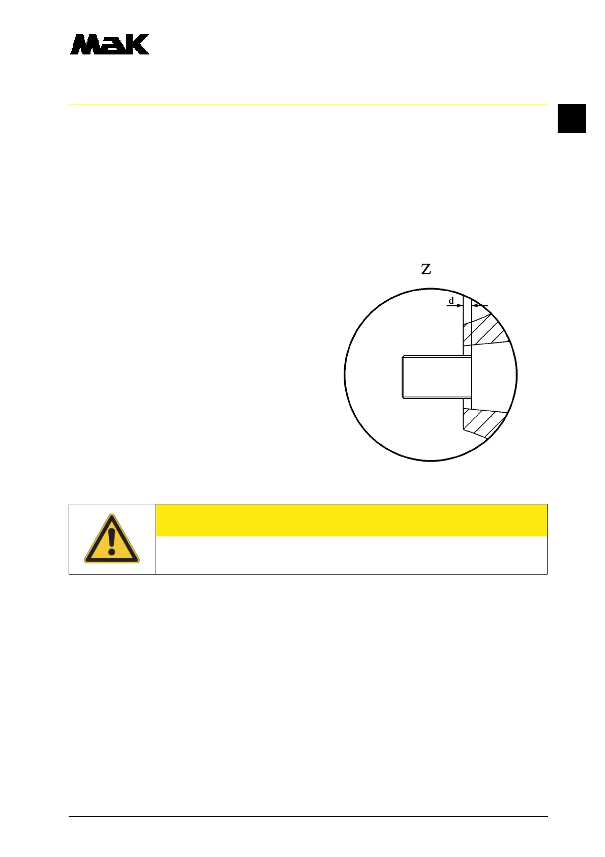
3.16 Reference dimension (Z)
d = 1.8 ± 0,1 mm
3.17 Mount the shim (16) , recess shows into
the direction of the impeller.
3.18 Mount the nut (15) nd tighten it with
M = 90 Nm
3.19 Lock the nut (16) with the 2nd nut (32)
and secure the nuts with loctite.
3.20 Insert new split ring (33) in the volute (11).
3.21 Put flat gasket (31) into the volute (11).
3.22 Mount volute (11) on the housing cover (12) in the correct position.
3.23 Before mounting the flywheel (2) (fig. 1/x) check bearing pattern between gear wheel cone and
shaft cone by spot-grinding. A uniformly distributed bearing pattern must be shifted to the thicker
end.
CAUTION
Lock impeller nuts with Loctite