Valve clearance
Inspection / Adjust
A5.05. 01.01.01.02
1500
M20
en / 30.09.2010 IB025384 2/2
01
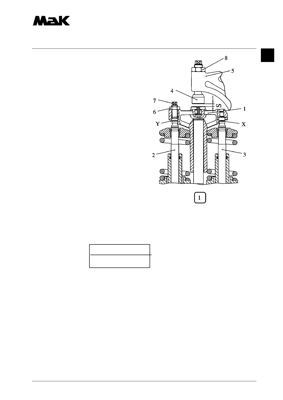
1.5 Release locknut (6) and unsrew setting
bolt (7) until a contact in „X”
without clearance is reached.
1.6 At this position of the valve bridge screw in
setting bolt (7) until contact at „Y” without
any clearance is reached.
Valve bridge must not be tited.
1.7 Hold tight setting bolt (7) and tighten lock-
nut (6) with
M = 30 Nm.
1.8 Check absence of clearance at „X“ and
„Y“ with feeler gauge of 0.02 mm (W1).
Afterwards adjust valve clearance „s“ as
per instruction.
2. Adjust valve clearance
2.1 Press the rocker arm (5) onto the push rod
and measure the clearance „s“ with the
feeler gauge.
2.2 Correct the clearance “s”:
2.2.1 Loosen counter nut (8).
2.2.2 Turn the valve adjusting screws (4) until the specified clearance ”s” has been attained.
Valve clearance „s“:
Inlet: 0.6 mm
Outlet: 0.8 mm
2.2.3 Tighten counter nut (8) with
M = 90 Nm
2.2.4 Check the clearance ”s” again.
2.3 Check the gaskets for the cylinder cover hoods and mount the cylinder cover hood.
2.4 Remove turning rod
2.5 Close decompression valves.