This document provides an instruction manual for the Makita Lockbolt Installation Tool models BV17-177 and BV13-177, which are also referred to as Lockbolt/Blind Rivet Installation Tools.
Function Description
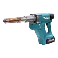
The Makita Lockbolt Installation Tool is designed for installing lockbolts and, in the case of the BV13-177 model, blind rivets. The tool operates by pulling the pin of the fastener to secure the collar or set the rivet, ensuring a tight and secure connection. The BV17-177 model is specifically for lockbolts without breaking off a mandrel, while the BV13-177 can handle both lockbolts with breaking off a mandrel and blind rivets. The tool features a control panel for adjusting the pulling force, allowing for precise application based on the fastener requirements. It also includes a front lamp for illuminating the work area and a battery protection system to extend tool and battery life.
Important Technical Specifications
| Model |
Pulling force |
Stroke |
Overall length (without pulling unit) |
Rated voltage |
Net weight (without pulling unit) |
| BV17-177 |
75 kN |
45.0 mm (1-3/4") |
497 mm (19-1/2") |
D.C. 36 V-40 V max |
7.8-9.3 kg (17.2-20.5 lbs) |
| BV13-177 |
55 kN |
45.0 mm (1-3/4") |
522 mm (20-1/2") |
D.C. 36 V-40 V max |
8.0-9.5 kg (17.6-20.9 lbs) |
Applicable Battery Cartridge and Charger:
The tool is compatible with BL4020, BL4025, BL4040, and BL4050F battery cartridges, with BL4025, BL4040, and BL4050F being recommended. Chargers include DC40RA, DC40RB, and DC40RC.
Usage Features
- Battery Installation/Removal: Battery cartridges are installed by aligning the tongue with the groove and sliding it into place until it locks. Removal involves sliding the button on the front of the cartridge and pulling it out.
- Remaining Battery Capacity Indication: Pressing the check button on the battery cartridge illuminates indicator lamps for a few seconds, showing the remaining capacity (75%-100%, 50%-75%, 25%-50%, 0%-25%, or charge the battery). A blinking first lamp indicates the battery protection system is active or the battery may have malfunctioned.
- Switch Action: The tool is activated by depressing the trigger-lock button from the A side and pulling the switch trigger. To stop, release the switch trigger. After use, depress the trigger-lock button from the B side to lock the switch trigger in the OFF position.
- Control Panel: The control panel allows for adjustment of the pulling force. To change the pulling force, press button A for a few seconds, then use button C to change the value and button B to change the digit. Press button A again to set the value, which can range from "000" to "999". The buttons can be locked by pressing buttons A and C simultaneously for a few seconds, indicated by "---" on the display.
- Front Lamp: Pulling the switch trigger activates the front lamp, which remains lit while the trigger is pulled and for approximately 10 seconds after release. The lamp blinks when the battery is low.
- Pulling Unit (Nose Assembly) Installation/Removal: The pulling unit consists of an anvil holder, sleeve, puller, lock nut, and nose adapter. Removal involves loosening the lock nut and anvil holder with wrenches, then sliding off the sleeve and loosening the puller. Installation is the reverse, ensuring the puller is fully inserted, the steel ball fits correctly in the groove, and all components are tightened securely.
- Side Grip Installation: The side grip can be attached to designated mounting areas on either side of the tool. It can be swung to different positions by loosening it counterclockwise, adjusting, and then tightening it clockwise.
- Eyebolt Installation: Eyebolts can be attached to both sides of the tool for hanging. It is crucial to ensure the eyebolt is undamaged, correctly sized, not excessively long or thin, and firmly secured. The eyebolt is not intended for lanyard (tether strap) use for fall prevention.
- Lockbolt Installation (without breaking off a mandrel) for BV17-177, BV13-177: Insert the pin into the hole, attach the collar, fit the puller onto the pin, and press the tool against the collar. Pull and hold the switch trigger until the tool stops tightening, indicating the collar is secured with the specified force. The puller automatically returns to its original position.
- Blind Rivet or Lockbolt Installation (with breaking off a mandrel) for BV13-177: Insert the blind rivet or lockbolt into the nose piece. Press the tool tip against the workpiece and pull the switch trigger. Release the switch trigger after the mandrel breaks off; the nose piece will return to its original position.
- Mandrel Container Emptying (for BV13-177): The mandrel container should be regularly emptied. To remove, rotate it counterclockwise. Installation is the reverse. For BV17-177, the rear cap should not be removed as it is not needed for mandrel collection.
Maintenance Features
- General Maintenance: Always ensure the tool is switched off and the battery cartridge is removed before any inspection or maintenance.
- Cleaning: Avoid using gasoline, benzine, thinner, alcohol, or similar substances, as these can cause discoloration, deformation, or cracks.
- Repairs: For product safety and reliability, all repairs, maintenance, or adjustments should be performed by Makita Authorized or Factory Service Centers, using genuine Makita replacement parts.
- Electric Brake: If the electric brake consistently fails to stop the tool quickly after the switch trigger is released, the tool should be serviced at a Makita service center.
- Battery Life Tips: Charge the battery cartridge before it is completely discharged. Stop operation and charge when tool power decreases. Never overcharge a fully charged battery. Charge at room temperature (10 °C - 40 °C). Allow hot battery cartridges to cool before charging. Remove the battery cartridge from the tool or charger when not in use for long periods (more than six months).
- Tool/Battery Protection System: The tool is equipped with protection systems for overload, overheat, and overdischarge. In case of overload, the tool stops without indication; turn it off, resolve the issue, and restart. For overheat, the tool stops and the lamp blinks; allow the tool and battery to cool. For overdischarge, the tool stops and the lamp blinks; remove and charge the battery.