P 16/ 19
Repair
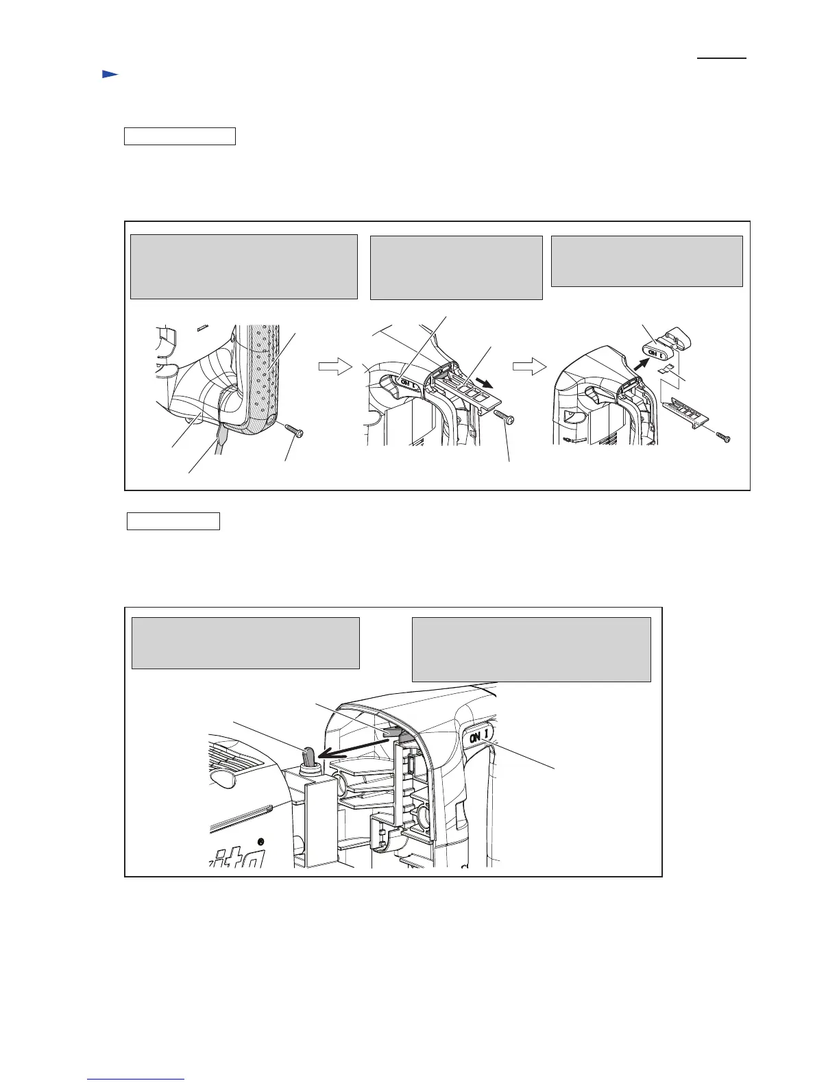
[3] DISASSEMBLY/ASSEMBLY
[3]-7. Switch lever, Slide lever in Handle
ASSEMBLING
Fig. 30
Fig. 31
(1) Assemble Slide lever and Switch lever to Handle section. Refer to Fig. 30.
(2) Assemble Handle to the machine as illustrated in Fig. 31.
(3) Assemble Handle cover to Handle. Refer to Fig. 30.
4x18 Tapping screw
DISASSEMBLING
(1) Separate handle section from the machine as per the left illustration in Fig. 4. Controller, Switch and Power supply
cord can be replaced in this step.
(2) Switch lever and Slide lever can be removed as illustrated in Fig. 30.
Unscrew 4x18 Tapping screw.
Remove Handle cover by levering up
with slotted screwdriver inserted into
the gap between Handle and Handle cover.
4x18 Tapping screw
Disconnect Switch lever from
Slide lever by unscrewing 4x18
Tapping screw. And remove
Switch lever.
Switch lever
Slide lever
Slide lever
Slide lever
Remove Slide lever as illustrated
below.
Do not lose Leaf spring in this step.
Handle cover
Handle
slotted screwdriver
Leaf spring
Switch lever
Mount Handle to the machine temporarily,
and check the engaging of Switch lever with
Lever of Toggle switch by operating Slide
lever.
Assemble Handle section to the machine
while engaging Switch lever with Lever
of Toggle switch.
Lever of Toggle
switch
 Loading...