P 9/ 19
Repair
[3] DISASSEMBLY/ASSEMBLY
[3]-4. AVT Mechanism of HM1317C, HM1317CB (cont.)
DISASSEMBLING
Fig. 15
Fig. 16
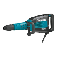
(3) Disassemble Ring spring 55 which secures the component parts for AVT mechanism as illustrated in Fig. 15.
Remove 2pcs. of O ring 45
from Cylinder 52.
And remove another
Ring spring 55
from Cylinder 52.
Remove the component parts for AVT as follows.
Weight guide (2pcs.) can be removed from
Counter weight in this step.
1R306
1R003 with
1R212
Shoulder
sleeve
Ring
spring 55
1R024
or
1R356
Set 1R306 to Arbor press.
Attach two pcs. of 1R024 or 1R356
to 1R306 keeping 67mm distance.
Stand the Cylinder on the
O ring 45 assembled side.
Pressing down Shoulder sleeve,
remove Ring spring 55.
1R024
or
1R356
Arbor Press
O ring 45
(2pcs.)
O ring 45
(2pcs.)
Shoulder
sleeve
Compression
spring 66
Compression spring 66
Drive sleeve
Weight guide
Counter weight
Cylinder 52
Cylinder 52
Ring spring 55
Ring spring 55
Rear cover
(with AVT mark)
Crank housing
ASSEMBLING
(1) Assemble ring spring 15 and 2 pcs. of O ring 45 to Cylinder 52. And then, assemble the component parts for AVT
mechanism. Refer to Figs. 16 and 15.
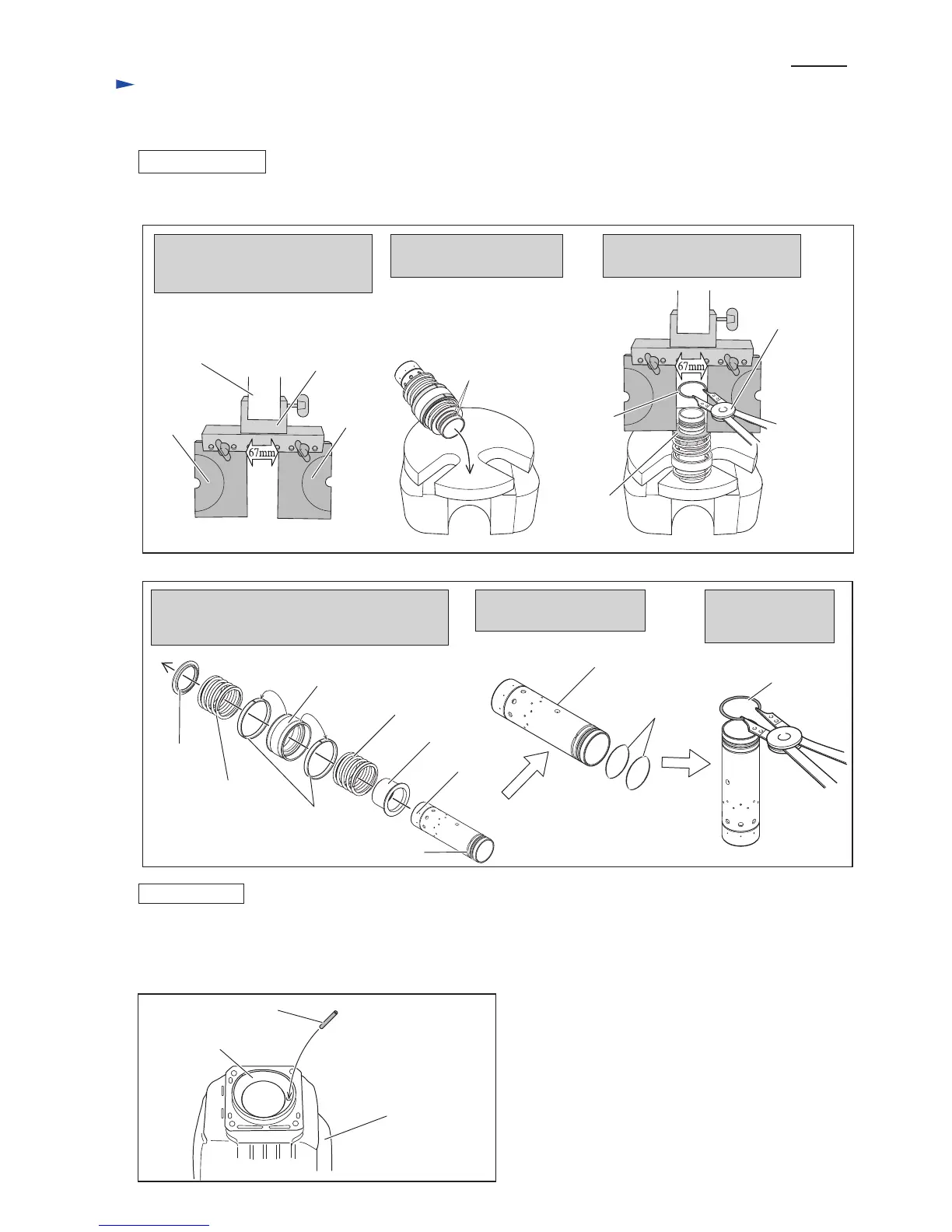
(2) Insert Pin 6 into the position illustrated in Fig. 17.
Pin 6
Fig.17
 Loading...