P 8 / 18
Repair
[3] DISASSEMBLY/ASSEMBLY
[3] -3. Disassembling/Assembling Barrel Section
DISASSEMBLING
ASSEMBLING
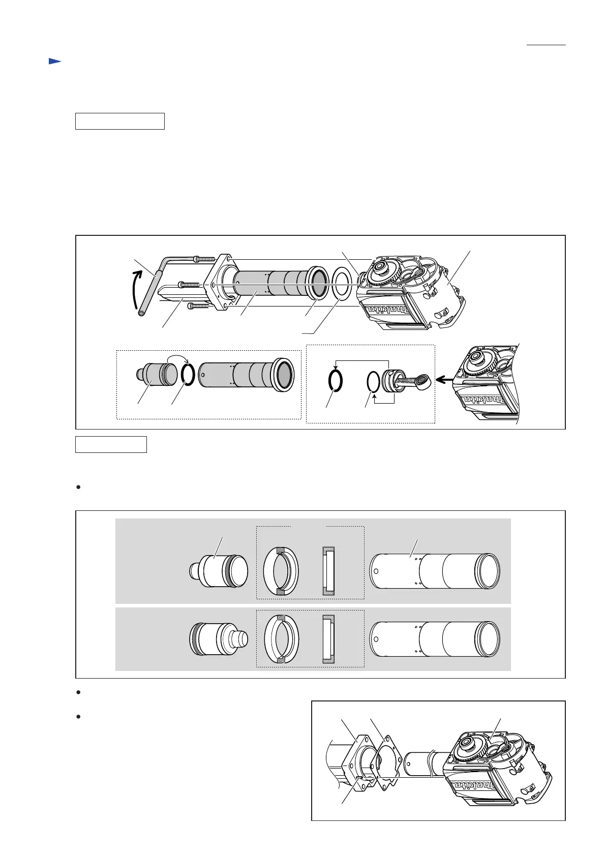
1) Remove Barrel from Crank housing complete by unscrewing four M12x55 Hex socket head bolts.
Then remove Cylinder liner 62. (Fig. 19)
Note: Use an appropriate steel pipe to extend the grip of hex wrench for easy removal of the bolts securely fastened
with adhesive.
2) Take out Striker from Cylinder liner 62, then remove O ring 52 from Striker. (Fig. 19)
3) Take out Piston and Connecting rod from Crank housing complete, and remove O ring 52 and O ring 55 from the
removed Piston. (Fig. 19)
Do the reverse of the disassembling steps.
Note:
Striker and Spacer are not reversible when assembled to Cylinder liner 62. Be sure to install as illustrated in Fig. 20.
Fig. 19
Fig. 20
Piston
Barrel Flat washer 63
Spacer
Crank housing comp.
Cylinder liner 62
Striker O ring 52
Steel pipe
[Tool retainer side]
[Crank housing side]
Cylinder liner 62
Spacer
Striker
Pin 5
Crank housing completeGasketBarrel
Fig. 21
CORRECT
WRONG
[Cross section]
Do not forget to put Flat washer 63 between Cylinder
liner 62 and Crank housing complete.
When assembling Barrel to Crank housing complete,
first fit Pin 5 in the hole on Barrel, and put the pin
through the hole of Gasket.
Then fit Barrel to Crank housing complete so that
Pin 5 is inserted into the hole on Crank housing
complete. (Fig. 21)
Piston and Connecting Rod
O ring 52 O ring 55

 Loading...