[3] DISASSEMBLY/ASSEMBLY
[3] -2. Gear assembly, Motor section
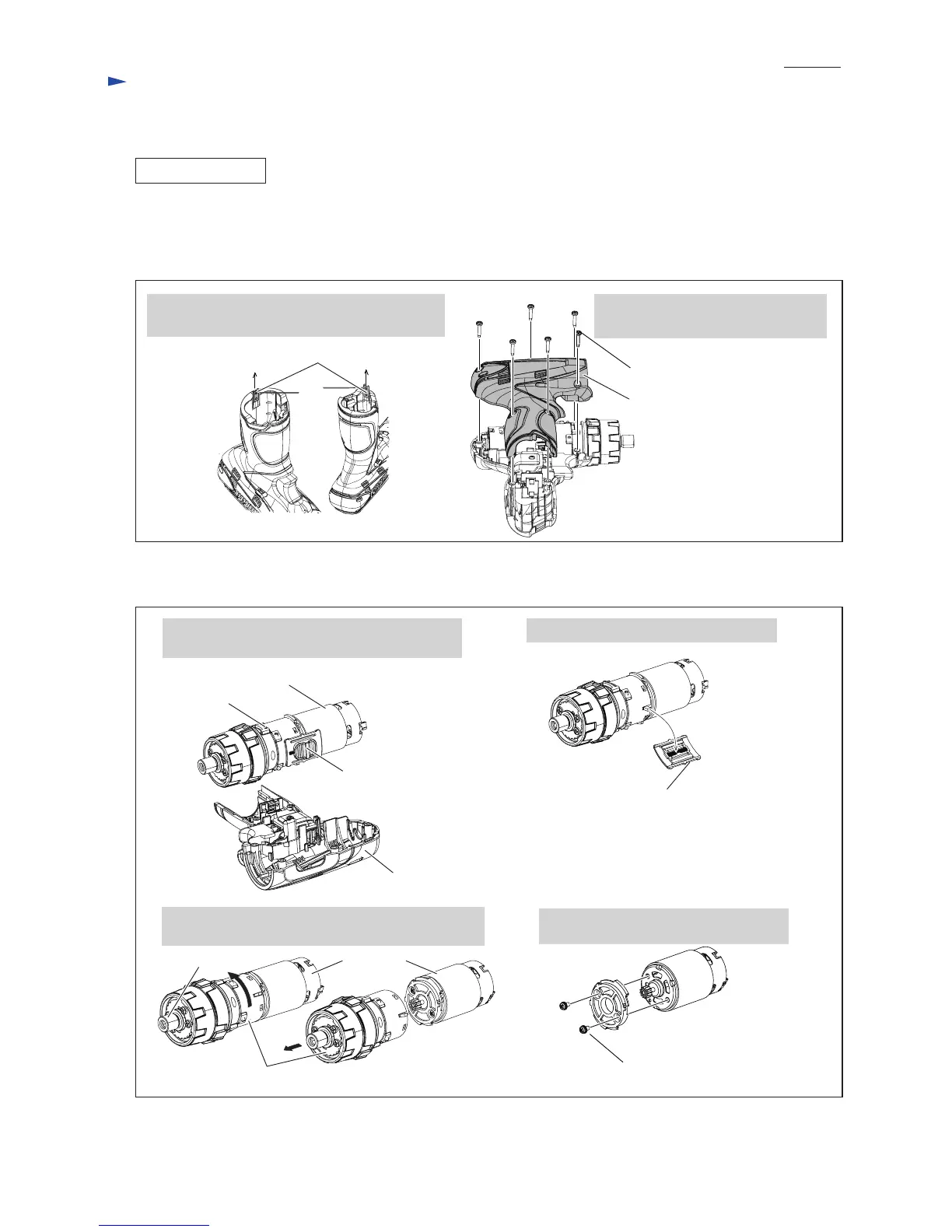
Fig. 9
DISASSEMBLING
(1) Remove Drill chuck. (Figs. 1, 2, 3)
Note: It is not required to remove Drill chuck when replacing only DC motor.
(2) Remove Housing R from Housing L. (Fig. 8)
(3) Separate DC motor from Gear assembly. (Fig. 9)
Fig. 8
1. Remove two Set plates by hooking the hole of
Set plate using small slotted screwdriver.
2. Remove Housing R by unscrewing
six 3x16 Tapping screws.
Set plate
Housing R
Housing R
Gear assembly
DC motor
Speed change lever
1. Remove Gear assembly, DC motor section and
Speed change lever together from Housing L.
2. Separate Speed change lever assembly.
3. Pull off Gear assembly, turning it counterclockwise
viewed from Spindle side.
4. Remove Motor bracket by unscrewing
two M3x6 Pan head screws.
Speed change lever
Gear assembly
Spindle
DC motor
Repair
P 5/ 11
3x16 Tapping screw (6 pcs.)
M3x6 Pan head screw (2 pcs.)
 Loading...