EasyManua.ls Logo

Makita HR4500C User Manual

Makita HR4500C
16 pages
To Next Page IconTo Next Page
Page #1 background imageLoading...
Page #1 background image
Specifications
CONCEPTION AND MAIN APPLICATIONS
Models No.
Description
PRODUCT
P 1 / 16
Dimensions : mm ( " )
Width (W)
Height (H)
Length (L)
118mm (4-5/8")
488mm (19-1/4")
For matured line-up of SDS-Max Rotary Hammers, Model HR4500C
has been developed as a sister model to HR4000C(40mm;1-3/4") and
HR5001C(50mm;2") which are already popular to users around the
world.
HR4500C
Rotary Hammer 45mm (1-3/4")
278mm (11")
Continuous Rating (W)
Voltage (V) Current (A) Cycle (Hz)
Input Output
Max. Output(W)
120
110 13 50/60 1,300 600 1,500
100 15 50/60 1,300 600 1,500
13 50/60
1,250
600
1,500
1,500
1,500
1,500
220 6.6 50/60
1,300 600
230 6.6 50/60
1,300 600
240 6.8
50/60 1,300 600
T
ECHINICAL INFORMATION
Performing excellent drilling in concrete within the diameter range
from 25mm(1") to 45mm(1-3/4"), it also has the same features and
benefits as HR4000C and HR5001C.
Hammer Grease (30cc), Blow-out Bulb, Dust Cup 5, Dust Cup 9, Bull Point, Cold Chisel, Scaling Chisel,
Clay Spade, Bushing Tool, Rammer, Safety Goggles, Core Bit Adapter,
Core Bits; Hole diameter : 20mm(13/16"), 30mm(1-3/16"), 35mm(1-3/8"), 40mm(1-9/16"), 45mm(1-3/4"),
54mm(2-1/8"), 65mm(2-9/16"), 79mm(3-1/8"), 105mm(4-1/8"), 118mm(4-5/8")
Tungusten-carbide Tipped Bits; Bit diameter : 10mm(3/8"), 10.5mm(7/16"), 11mm(7/16"), 12mm(15/32"),
12.5mm(1/2"), 12.7mm(1/2"), 13.5mm(1/2"), 14.3mm(9/16"),
14.5mm(9/16"), 16mm(5/8"), 17mm(11/16"), 17.5mm(11/16"),
18mm(11/16"), 19mm(3/4"), 20mm(13/16"), 21.5mm(7/8"),
22mm(7/8"). 24mm(15/16"), 25mm(1"), 25.4mm(1"), 26mm(1"),
28mm(1-1/8"), 30mm(1-3/16"), 32mm(1-1/4"), 35mm(1-3/8"),
38mm(1-1/2")
120 - 240
1,250 - 2,550
SDS-Max shank bit
18 (11/16")
No load speed
Rotations per minute : rpm=min-1
Blows per minute : bpm=min-1
Bit type
Diameter of shank : mm (")
Drilling capacities
: mm (")
Net weight : Kg (lbs)
Cord length : m (ft)
7.8 (17.2)
Standard spec. : 5 (16.4)
European spec. : 4 (13.1)
STANDARD EQUIPMENT
45 (1-3/4")
Tungusten-carbide
tipped bit
Core bit
125 (4-7/8")
Grip 36 Assembly
(Bar style side handle) ------------ 1pc.
Depth Gauge ----------------------- 1pc.
Grease Vessel (Bit Grease) ------- 1pc.
Plastic Carrying Case ------------- 1pc.
Side Handle Assembly
(D-shaped side handle) ----------- 1pc.
OPTIONAL ACCESSORIES
The standard equipment for the machine may differ from country to country.
See next page for detailed information.
L
W
H

Other manuals for Makita HR4500C

Question and Answer IconNeed help?

Do you have a question about the Makita HR4500C and is the answer not in the manual?

Makita HR4500C Specifications

General IconGeneral
Voltage240V
Chuck TypeSDS-Max
Max. Drilling Capacity (Concrete)45 mm
Max. Drilling Capacity (Core Bit)125 mm
Max. Drilling Capacity (Steel)13 mm
Vibration ControlYes
Anti-Vibration TechnologyAVT (Anti-Vibration Technology)
Power SourceCorded Electric

Summary

Conception and Main Applications

Specifications

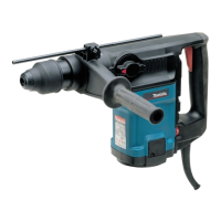
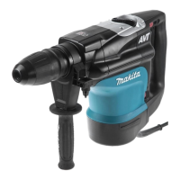
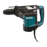
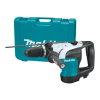
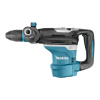
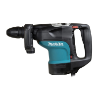
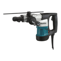
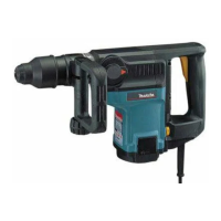
Technical details including voltage, current, capacity, and dimensions for the rotary hammer.

Standard Equipment

List of included accessories provided with the machine.

Optional Accessories

List of additional accessories available for purchase.

Features and Benefits

Outstanding Chipping Power

Highlights the rotary hammer's superior chipping performance in its class.

Resin-Coated Body and Armature Coil

Details the protective resin coating for safety and durability.

Key Operational Features

Summarizes essential features like no hammering while idling and speed control.

Product Comparison

Chipping Amount Comparison

Compares chipping performance against competitor models.

Drilling Speed Comparison

Compares drilling speeds for various hole sizes against competitors.

Detailed Product Specifications Comparison

Presents a table comparing product specifications across different models.

Repair Procedures

Lubrication

Instructions for applying Makita grease to specific parts for maintenance.

Disassembling Change Lever Complete

Steps for safely removing the change lever assembly.

Assembling Change Lever

Guidance on correctly assembling the change lever mechanism.

Disassembling Armature

Procedure for removing the armature from the motor housing.

Disassembling Handle and Components

Steps for disassembling the handle, controller, and related parts.

Disassembling Motor Housing and Armature

Instructions for separating the motor housing and armature.

Assembling Armature

Process for assembling the armature into the gear housing.

Disassembling Chuck Section

Steps for taking apart the chuck assembly.

Assembling Chuck Section

Guidance on reassembling the chuck components.

Disassembling Tool Holder

Procedure for removing the tool holder from the crank housing.

Disassembling Lock Sleeve A and B

Steps for removing lock sleeves A and B from the tool holder.

Disassembling Torque Limiter Section

Procedure for disassembling the torque limiter components.

Disassembling Crank Shaft

Steps for separating the crank shaft from the crank housing.

Disassembling Cylinder

Procedure for removing the cylinder using a specialized extractor.

Assembling Reciprocating Section

Process for assembling the piston, cylinder, and crank shaft.

Assembling Fluoride Ring to Impact Bolt

Instructions for correctly assembling the fluoride ring onto the impact bolt.

Assembling Crank Housing Section

Guidance on assembling spare parts into the crank housing.

Assembling Tool Holder Section

Process for assembling the tool holder with its components.

Assembling Torque Limiter Section

Steps for assembling the torque limiter onto the spiral bevel gear.

Diagrams and Schematics

Circuit Diagram

Schematic illustrating the electrical connections of the tool's components.

Wiring Diagram

Diagram showing the routing and connection of internal wiring.

Related product manuals