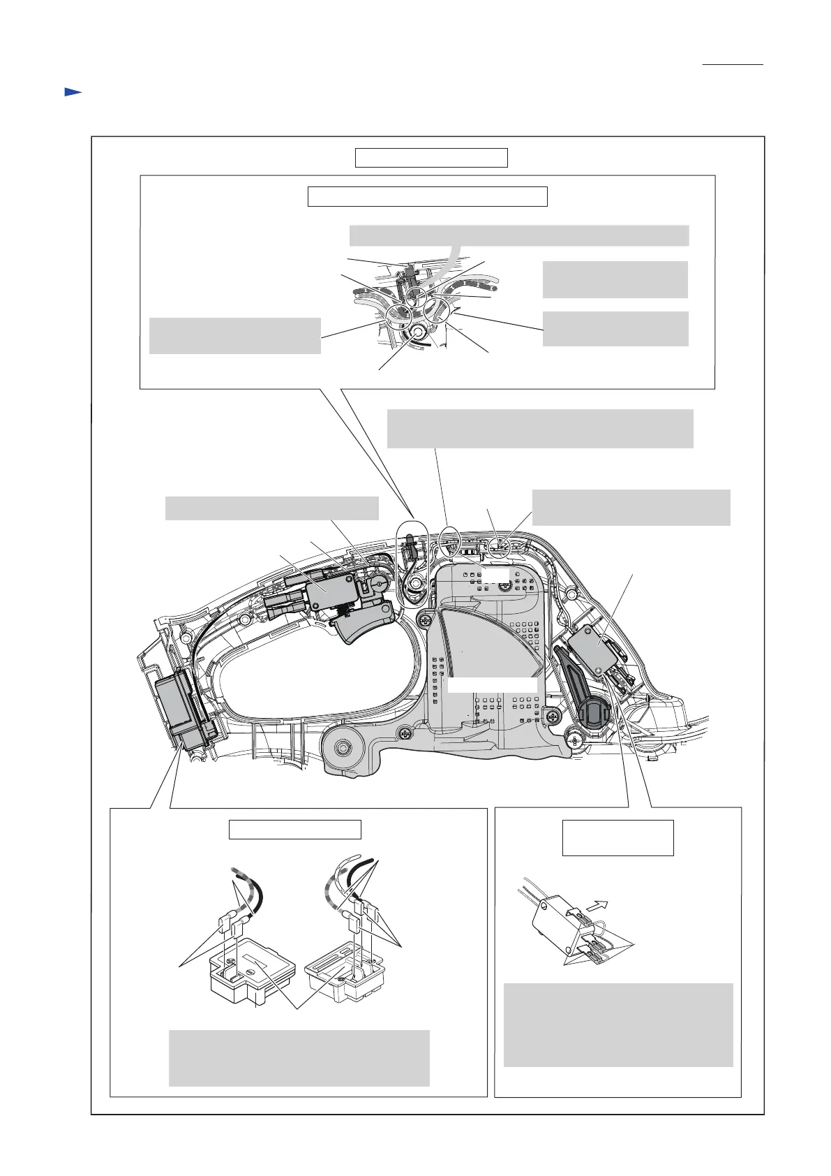
Wiring in Housing set
Fig. D-5
Lead wire
holder
Fix the Lead wires (white, orange,
purple) with Lead wire holder.
Switch on Front
grip side
Wiring to Switch
on Front grip side
Switch
Do not put the Lead wires on this Rib.
Motor housing
Rib
Rib
Face their connectors to Housing L side
and connect their lead wires to Switch
terminals.
Their lead wires have to be routed
between Housing L and Switch.
Connectors
Receptacle
Housing L side
Wiring of LED warning lamp for battery
Rib A
LED Lamp
Rib C
Groove
Face the projected portion of LED Lamp to Front grip side.
Boss
Put LED Lamp’s Lead
wires into groove.
Put the following Lead wires
between Rib A and Boss.
Put Lead wires between
Rib B and Rib C.
Wiring to Terminal
Flag connectors have to be connected so that
their lead wires are passed over the center of
Terminal.
Flag connector
Lead wires
Lead wires
the center of Terminal
Flag connector
Rib B
Route the Lead wires (white, orange, purple) between
the Rib and inner wall of Housing set.
Wiring diagram (cont.)
P 13/ 13

 Loading...