P 6/ 9
Repair
[3] DISASSEMBLY/ASSEMBLY
[3]-2. Armature, Switch (cont.)
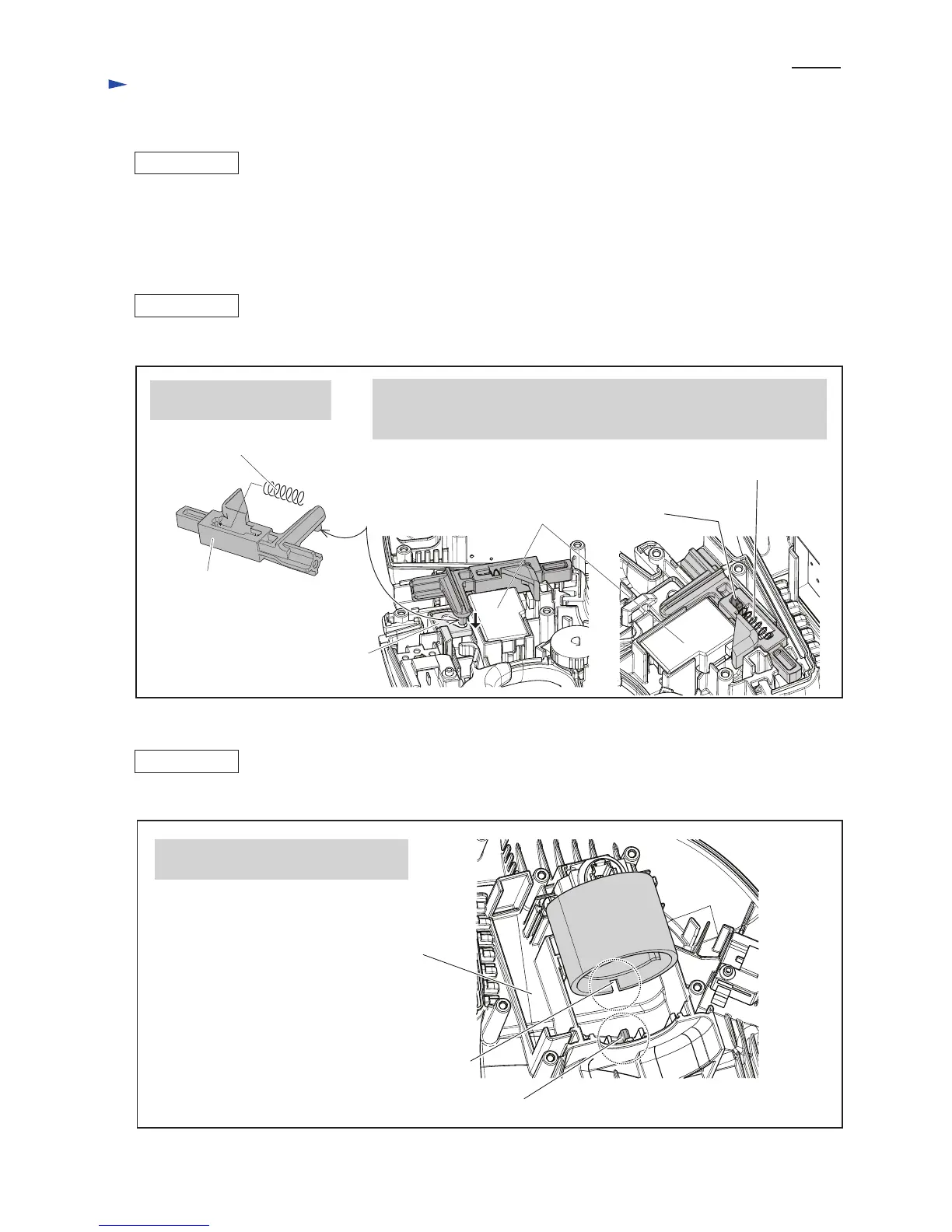
Mount Compression spring 6
to Lock lever.
Fig. 9
Fig. 10
ASSEMBLING
(1) Mount the Switches to Handle L complete and Housing L complete by taking the reverse step of Disassembling.
(Fig. 8)
(2) Armature can be assembled by taking the reverse step of Disassembling. (Figs. 7, 6)
(3) Assemble Gear complete. (Fig. 4) And then, mount Shear blade assembly. (Figs. 3, 2)
Notch of Yoke unit
Housing L complete
Protrusion of Housing L complete
Fit the protrusion of Housing L complete
into the groove of Yoke unit.
Assemble Yoke unit to Housing L complete. (Fig. 10)
[3]-3. Lock Lever
[3]-4. Yoke Unit
ASSEMBLING
ASSEMBLING
Compression spring 6
Pin of
Lock lever
Rib of Handle L
complete
Inserting the pin of Lock lever into the elliptical hole of Slider,
assemble Lock lever so that the rib of Handle L complete comes to
the place between Compression spring 6 and Lock lever as drawn in right.
Elliptical hole of Slider
Handle switch
Lock lever
Compression spring 6
Reassemble Lock lever. (Fig. 9)
 Loading...