Wiring diagram
P 8/ 9
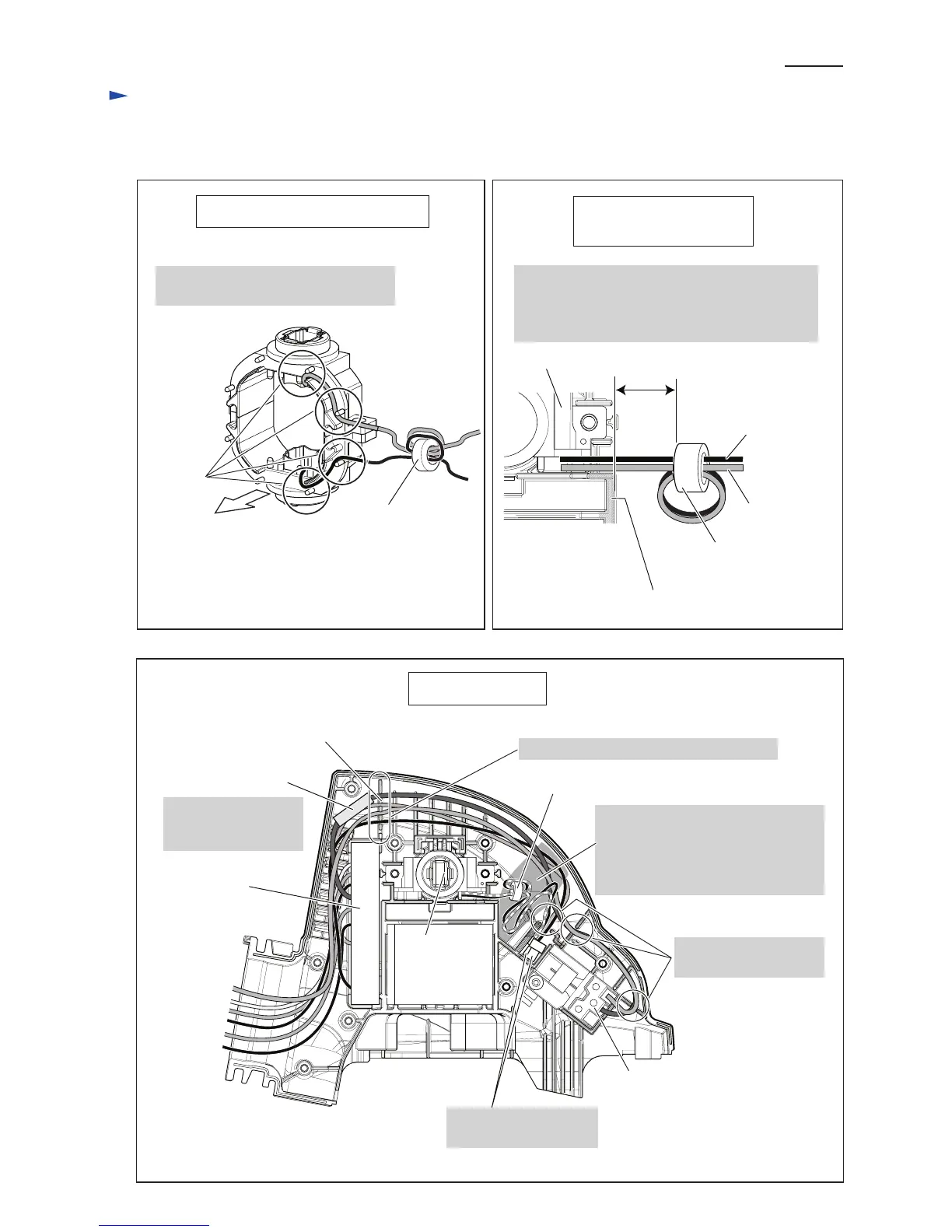
Fig. D-2
Fig. D-3
Line Filter and Brush
holders’ Lead wires
Lead Wires of Brush Holder
max.
30 mm
Lead wire (black)
of Brush holder
Lead wire (red) of
Brush holder
• Line filter’s position has to be adjusted that it
distances max. 30 mm from the rib for Yoke unit.
• Two lead wires from Brush holder have to be
coiled around Line filter one turn.
Rib for Yoke unit
Fix Lead wires with Lead wire holders
on Yoke unit side.
Yoke unit side
Line filter
(if used)
Line filter (if used)
Lead wire
holders
Brush holder
Fig. D-4
Motor Housing
Front grip switch
Line Filter (if used)
Line Filter (if used)
Put Line filter between
Lead wire holder and
Controller.
Controller
Put Insulated connectors
in this place.
Fix Lead wires in these Lead wire holders.
Brush holder
Fix Lead wires in
these Lead wire holders.
• Lead wires (black, red) to Insulated
connector have to be passed through
Line filter.
• Slack portion of lead wires have
to be stored in this place.
Lead wire holder
 Loading...