Do you have a question about the Malaguti F12R L.C. 50 cc and is the answer not in the manual?
Information on manual updates and easy consultation procedures.
Explains page structure, symbols, and abbreviations for clarity.
Details various symbols used for caution, hazards, maintenance, and references.
Provides notes on screw notation and essential stability precautions before servicing.
Identifies various electrical components and their locations on the vehicle.
Provides a key to understand the wire colours used in the diagram.
Lists and numbers components referenced in the general wiring diagram.
Details the pinout and wire assignments for the instrument board connector.
Outlines methods for testing switches and illustrates connection diagrams.
Illustrates the positions and wiring for handlebar-mounted switches.
Procedures for checking fuse continuity and guidelines for replacement.
Steps to check spark plug condition and cap resistance.
Procedures for measuring resistance of CDI unit and stator pick-up.
Verifying key switch continuity and overall ignition system connections.
Procedures for checking the starting system's fuse and battery condition.
Steps to test the operation of the starter motor and starting relay.
Procedures for checking the key switch and front/rear stop switches.
Verifying the start switch function and overall system connections.
Checking the charging system fuse and battery charging voltage.
Measuring charging coil resistance and verifying system connections.
Checking the lighting system fuse and lighting coil resistance.
Verifying continuity of cables and testing the voltage regulator.
Checking bulb continuity and voltage delivered to lamp sockets.
Measuring voltage delivered to the instrument board indicator lights.
Checking rear lamp continuity and voltage at the socket.
Checks for fuse continuity, battery condition, and key switch function.
Tests horn switch, voltage delivery, and grounding.
Verifies stop light fuse, brake switches, and voltage at bulb.
Checks turn indicator fuse, switch, and voltage at lamps.
Verifies mode button continuity, voltage, and cable connections.
Measures H2O probe resistance and checks oil sensor and voltage.
Tests fuel probe resistance and cable continuity.
Checks rev counter sensor voltage, instrument signal, and cable continuity.
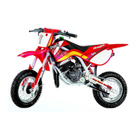
| Engine Type | Single cylinder, 2-stroke |
|---|---|
| Displacement | 49.2 cc |
| Cooling System | Liquid cooled |
| Fuel System | Carburetor |
| Front Suspension | Telescopic fork |
| Front Brake | Disc |
| Rear Brake | Drum |
| Weight | 97 kg |
| Transmission | CVT |
| Rear Suspension | Single shock absorber |