Do you have a question about the Mallinckrodt Nellcor N-20 and is the answer not in the manual?
Overview of the service manual's purpose and scope.
Defines WARNING and CAUTION terms used in the manual.
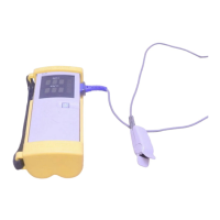
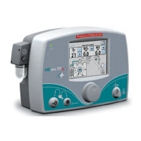
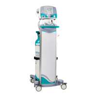
Describes the N-20/N-20P portable pulse oximeters and their functions.
Outlines that the N-20/N-20P requires no routine maintenance.
Instructions for cleaning the exterior surfaces of the N-20/N-20P.
Recommends checks every 2 years by a qualified service technician.
Guidance on battery removal for storage and replacement.
Introduces performance verification tests for the N-20/N-20P after repairs.
Lists necessary materials for performance verification.
Outlines tests for instrument performance using a tester.
Describes how to test the electroluminescent backlight.
Details testing the monitor's battery operating time.
Verifies the self-test function during power-on.
Step-by-step guide to running the power-on self-test.
Procedure to test the N-20P printer and its user controls.
Covers tests related to hardware and software operation.
Details using the pulse oximeter tester for normal operation verification.
Qualitative check using a live subject to verify system operation.
Explains how to use the troubleshooting section for identifying and correcting difficulties.
Specifies that only qualified service personnel should perform repairs.
Defines supported replacement levels as PCBs and major subassemblies.
Directs users to contact Mallinckrodt Technical Services for parts.
Discusses potential symptoms, causes, and resolutions for N-20/N-20P issues.
Covers common service procedures encountered by technicians.
Step-by-step instructions for installing batteries into the unit.
Procedures for loading and clearing paper from the N-20P printer.
Procedure for setting the date and time on the N-20P.
Steps to replace the RTC battery on the auxiliary PCB.
Information on replacing fuses F1 and F2 on the auxiliary PCB.
Procedure for replacing the DB-9 connector on the main PCB.
Instructions for adjusting the printer darkness setting.
Explains error messages and 3-digit codes displayed during failures.
Lists and describes microprocessor error codes (101-129).
Lists RAM memory error codes and suggested actions.
Describes printer errors and the "Pr Err" display.
Introduces the disassembly process and key component parts.
Lists the necessary tools for disassembly and repair.
General procedure for N-20 disassembly, emphasizing safety.
Detailed steps for removing the front and rear covers of the instrument.
Steps for removing the main, auxiliary PCBs, and display assembly.
Specific disassembly steps for the N-20P model.
Procedures for disassembling the printer and flex circuit components.
Lists spare parts with designators, descriptions, and part numbers.
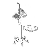
Provides general instructions for carefully packing the monitor for shipment.
Instructions for repacking the unit using the original carton and materials.
Instructions for repacking the unit in a different carton if the original is unavailable.
Describes the information displayed by the unit, including indicators.
Details the functions of the Measure and Battery-Check buttons.
Explains the Spot Check and Extended modes of operation.
Describes how to initiate and what happens in Spot Check mode.
Describes how to initiate and what happens in Extended mode.
Details the output provided by the N-20P printer.
Specifies performance ranges and accuracy for SpO2 and pulse rate.
Defines the measurement ranges for SpO2 and pulse rate.
Details the SpO2 accuracy specifications for adults and neonates.
Describes the response time in different operating modes.
Lists compatible sensor types, models, and patient sizes.
Details electrical specifications like battery type and instrument power requirements.
Specifies battery type and capacity.
Details power requirements and leakage current.
Lists operating and storage temperature, humidity, and altitude limits.
Specifies the instrument's operating temperature range.
Specifies the storage temperature range.
Provides weight and dimensions of the N-20 and N-20P.
Lists the weight of the N-20 and N-20P with batteries.
Lists the dimensions of the N-20 and N-20P.
Explains calibration basis and factors affecting accuracy.
Explains the principles of operation for the N-20/N-20P.
Explains the difference between functional and fractional saturation measurements.
Discusses differences between N-20/N-20P saturation and blood gas calculations.
Introduces the discussion of the N-20/N-20P circuits.
Explains N-20/N-20P operation using block diagrams and schematics.
Details the SpO2 analog circuitry, consisting of four subsections.
Shows the digital hardware and circuits of the N-20/N-20P.
Illustrates the power supply circuitry on the auxiliary PCB.
Explains how the display control circuitry manages the unit's display.
Details the printer control circuitry and its interface.
Defines key terms used in the technical supplement.
Defines the A/D converter's role and capabilities in the CPU.
Defines the CPU as an Intel 80C196KC 16-bit microcontroller.
Defines CAM and its control by the CPU.
Defines HSO lines and their function in timing control.
Defines I/O as digital lines for data transfer.
Describes the LEDs used in sensors and their wavelengths.
Defines PWM outputs and their control over analog circuits.
Defines RCal as a sensor-specific resistance value used for accuracy.
Defines the RTC and its use for tracking time/date.
Illustrates the overall system block diagram.
Lists components and functions of the main PCB.
Lists components and functions of the auxiliary PCB.
Describes the display assembly, its connection, and backlight.
Details the SpO2 analog circuitry and its subsections.
Explains CPU control of LED gain and current for signal acquisition.
Details conversion of sensor current to voltage and signal filtering.
Explains amplification of signals to meet A/D converter range.
Details elimination of DC offset and AC modulation for signal processing.
Discusses CPU control of LEDs and signal gain to match A/D converter range.
Details the LED drive circuit, including current control and switching.
Explains sensor current conversion to voltage and noise reduction.
Describes the circuit used to reduce noise and effects of light sources.
Explains amplification and filtering to prepare signals for the A/D converter.
Illustrates the variable gain circuits controlled by PWM signals.
Details AC ranging for signal measurement and comparison.
Explains voltage dividers and amplifiers for establishing a baseline voltage.
Illustrates AC variable gain circuits for signal amplification.
Details the digital hardware and related circuitry.
Describes the CPU as a 16-bit microcontroller with peripherals.
Details the static RAM and EPROM used for system memory.
Explains the RTC's function for timekeeping and non-volatile memory.
Describes the piezoelectric ceramic beeper for audio output.
Explains display control, including ambient light sensor and backlight.
Describes the Measure and Battery-Check buttons.
Details the power supply and control circuitry connected to batteries.
Describes the thermal printer's function and ambient temperature sensor.
Details the CPU circuit and its capabilities.
Explains the address demultiplexing circuit using transparent latches.
Details the address decoding circuit for RAM, EPROM, and I/O ports.
Illustrates the CPU memory circuit with SRAM and EPROM.
Describes the input port circuit for user controls and battery type sensing.
Describes the output port circuit for display, audio, and printer control.
Explains the RTC circuit for timekeeping and non-volatile storage.
Describes the audio output circuit using a piezo ceramic sounder.
Details the display control circuitry, including photosensor and drivers.
Explains the circuit that generates timing signals for display drivers.
Describes the display driver ICs that control display segments.
Explains the circuit that enables/disables display high voltage.
Details display driver chips, data loading, and segment illumination.
Explains the cold switch circuit for display voltage control.
Describes the circuit for the push-button user controls.
Details the power supply and control circuitry.
Explains the power control circuit using a flip-flop for power management.
Describes the power shutoff circuit and fuse protection.
Details the Vcc power supply, a switched inductor voltage regulator.
Describes the raw power supplies generated by a switched-capacitor converter.
Details the high voltage supply for display drivers.
Illustrates the analog reference voltage circuit.
Explains the ambient light circuit and its role in backlight control.
Describes the ambient temperature sensor circuit.
Details the battery voltage sensing circuit and low battery detection.
Explains the battery type sensing circuit for rechargeable/disposable batteries.
Details the printer interface and flex circuit for N-20P operation.
Describes the printer interface circuit and its protection.
Describes the printer flex circuit and its role in controlling the printer.
Illustrates the printer interface circuit.
Details the printer flex circuit and its user controls.
Lists illustrations that support the manual's descriptions.
| Brand | Mallinckrodt |
|---|---|
| Model | Nellcor N-20 |
| Category | Medical Equipment |
| Language | English |