9
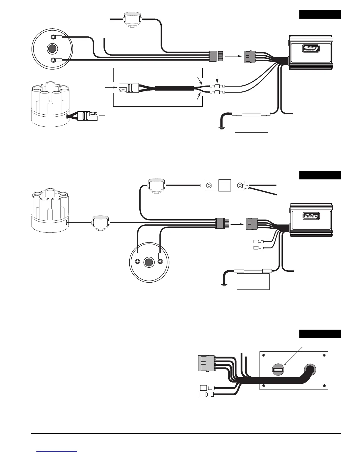
IGNITION
CONTROL
PLUG
IGNITION
CONTROL
HARNESS
LONG BLACK
(–) BATTERY (+)
LONG RED
SMALL
BLACK
SPADE TERMINAL
CONNECTORS
SMALL
GREEN
GREEN (NOT USED)
RED
BLACK
YELLOW
IGNITION COIL
SMALL BLACK / MAG –
SMALL RED / MAG +
ALL WIRES NORMALLY CONNECTED
TO THE COIL (+) TERMINAL
CHASSIS/FRAME GROUND
(DO NOT CONNECT TO
ENGINE BLOCK)
HYFIRE
®
IGNITION
SYSTEM
®
MOPAR / CHRYSLER
ADAPTER PART NO. 29040
ADAPTER PART NO. 29040
+
–
FIGURE 13
IGNITION COIL
GREEN
BLACK YELLOW
IGNITION CONTROL
HARNESS
OEM BALLAST OR
MALLORY BALLAST
RESISTOR (PN. 700)
NOTE: DO NOT DISCONNECT CONDENSOR
+12 VOLTS FROM IGNITION SWITCH
ALL OTHER WIRES ORIGINALLY
CONNECTED TO THE COIL (+) TERMINAL
RING TERMINAL
CONNECTOR
RING TERMINAL
CONNECTOR
BREAKER POINT DISTRIBUTOR
RED
+–
IGNITION
CONTROL
PLUG
LONG BLACK
(–) BATTERY (+)
LONG RED
CHASSIS/FRAME GROUND
(DO NOT CONNECT TO
ENGINE BLOCK)
HYFIRE
®
IGNITION
SYSTEM
®
SMALL GREEN AND BLACK
WIRES – NOT USED
FIGURE 14
Step 3
Tachometer Operation:
If a tachometer is used, connect tachometer ignition sensing lead to the TACH terminal on the
HYFIRE
®
IV Electronic Ignition Control.
If the tachometer does not work after being connected to the TACH terminal, connect the
tachometer ignition sensing lead to the GREEN WIRE from the Ignition Control Harness.
Install the Mallory Fuel Injection and Tachometer Adapter Part No. 29074 to supply the
proper signal for the tachometer to operate.
Step 4
Secure all wires with cable ties to prevent contact extreme heat, sharp objects or moving
devices such as fans, belts and linkages.
Step 5
Recheck all wire and connections to ensure they are correct before applying power.
Step 6
Connect the battery () terminal cable. Start engine and check operation of the ignition system.
TACH/RPM OUTPUT
MAGNETIC
PICKUP
IGNITION CONTROL
FIGURE 15
 Loading...