Do you have a question about the Mamiya PD Prism Finder S and is the answer not in the manual?
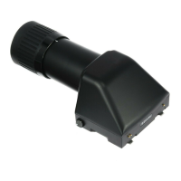
| Type | Prism Finder |
|---|---|
| Compatibility | Mamiya 645 series cameras |
| Metering | TTL metering |
| Eyepoint | 25mm |
| Diopter Adjustment | -3 to +1 diopters |
Finder integrates a silicon diode and electronic shutter control circuit for advanced functionality.
Finder allows complete coupling with the camera's lens, ISO speed, and shutter.
Utilizes seven LEDs for exposure interpretation: yellow-green for correct, red for over/under/compensated.
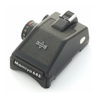
Unreversed, laterally correct image, 0.74x magnification, built-in hot shoe, removable eyecup.
Center-weighted TTL full aperture, one yellow-green and six red LEDs in viewing system.
EV 1.15 to 19, specified for f/1.9 and f/2.8 lenses and ASA 100.
1/1000 sec. to 8 sec. Shutter speed on finder dial, not camera.
Ensure the White Dot on the Finder Release Button points upward before attachment.
Place the rear of the finder on the camera body with the front slightly upward.
Lower the front of the finder and push downward to lock it onto the camera body.
Gently lift the finder to confirm it is securely latched to the camera body.
Push the Finder Release Button and lift the finder off the camera body.
Set lens A-M lever to 'A' and engage the Aperture Ring with the lens's Aperture Coupler.
Pull out and rotate the finder's ISO dial to display the film's ASA speed in the window.
Set the camera's Shutter Speed Dial to its Concentric Circle setting for electronic coupling.
Always set shutter speed on the finder's dial, not the camera's.
Activate meter circuit via Meter Switch; turn lens Aperture Ring for yellow-green LED.
If correct exposure isn't met, adjust Aperture Ring until yellow-green LED is illuminated.
Set the lens' Aperture Ring to the desired aperture.
Adjust exposure by turning the finder's Shutter Speed Dial until the center yellow-green LED illuminates.
Set the desired shutter speed on the finder's Shutter Speed Dial.
Turn the lens' Aperture Ring until the viewfinder's center yellow-green LED is illuminated.
Seven LEDs display exposure in 1 EV increments; center is yellow-green, others are red.
Two LEDs illuminated simultaneously; adjust Aperture Ring until only the center yellow-green LED is lit.
Three upper red LEDs illuminated; uppermost indicates 3 EV or more overexposure.
Three lower red LEDs illuminated; lowermost indicates 3 EV or more underexposure.
Exposure compensation is generally unnecessary with TTL metering when using filters or extension rings.
Adjust indicated exposure by +1 stop for strongly backlit subjects outdoors.
Adjust indicated exposure by +2 stops for subjects seated in front of a brightly lit window.
Adjust indicated exposure by +1 to +2 stops for bright interior lights.
Adjust indicated exposure by +2 stops when copying white documents.
Adjust indicated exposure by -1 to -2 stops for subjects against a dark background.
Adjust indicated exposure by -1 stop when photographing extremely dark subjects.
Correction lenses available for farsighted (+3, +1, +1) and nearsighted (-0.5, -1, -2, -3, -4) users.
Remove the finder's Eyecup before proceeding with lens installation.
Remove the finder's Diopter Corrective Lens Retaining Ring.
Insert the Corrective Lens into the finder's Eyecup Frame.
Reinstall the Diopter Corrective Lens Retaining Ring and then the Eyecup.
Remove the finder's Eyecup to begin the lens removal process.
Remove the finder's Diopter Corrective Lens Retaining Ring.
Carefully remove the Diopter Corrective Lens from the finder's Eyecup Frame.
Reinstall the Diopter Corrective Lens Retaining Ring and then the Eyecup.