The camshafts are located in bearing bushes which
are fitted in bores in the engine frame; each bearing
is replaceable and locked in position in the engine
frame by means of a locking screw.
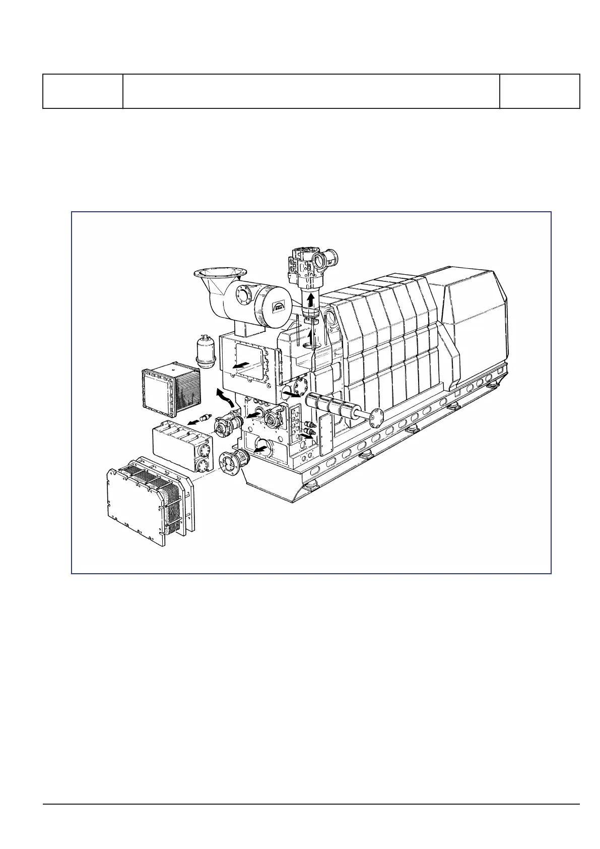
Figure 7: Front-end box.
The gear wheel for driving the camshaft as well as a
gear wheel connection for the governor drive are
screwed on to the aftmost section.
The lubricating oil pipes for the gear wheels are
equipped with nozzles which are adjusted to apply
the oil at the points where the gear wheels are in
mesh.
Front-end box
The front-end box is fastened to the front end of the
engine. It contains all pipes for cooling water and
lubricating oil systems and also components such
as pumps, filters, coolers and valves.
The components can be exchanged by means of
the clip on/clip off concept without removing any
pipes. This also means that all connections for the
engine, such as cooling water and fuel oil, are to be
connected at the front end of the engine to ensure
simple installation.
Governor
The engine speed is controlled by a hydraulic or
electronic governor with hydraulic actuators.
MAN Diesel & Turbo
1689477-8.1
Page 5 (7)
General description
B 10 01 1
L27/38S, L27/38
2015.11.26
 Loading...