4 0 5 0 6 0 7 0 8 0 9 0 1 0 0 11 0
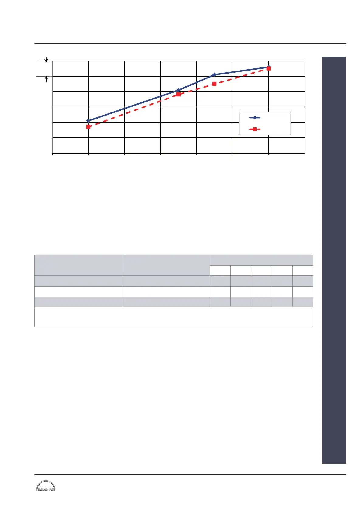
Engine thermal efficiency in %
MCR Maximum Continuous Rating
Figure 5: Improvement of the thermal efficiency with a TCA55-41V on an 7L51/60DF engine
1.3 Low-speed propulsion engines from MAN B&W
The following tables summarize the fuel-saving potential existing for
MAN B&W engines. All SFOC values refer to the SFOC for a load of 100%
for a standard L
1
engine.
SFOC-optimized load range Tuning method SFOC change [g/kWh]
35% 50% 65% 80% 100%
High load (85-100%) Standard L
1
engine 3.5 -1 -3.5 -3.5 0
Partial load (50-85%) VTA 0.5 -4 -6.5 -4.5 0.5
Low load (25-70%) VTA -1.5 -6 -8.5 -3.5 0.5
Standard L
1
engine – turbocharger without adjustable turbine nozzle ring
VTA – turbocharger with adjustable turbine nozzle ring
Table 8: Optimization potential – ME/ME-C Tier II engines, SMCR = L
1
2013-12-04 - de
1 Adjustable turbine nozzle ring (VTA)
1.3 Low-speed propulsion engines from MAN B&W
MAN Diesel & Turbo
1
EN-US
11 (38)