5 Engine room planning
5.1 Equipment
There are various specifications for installation of the components required
for operation of an adjustable turbine nozzle ring.
See chapter Scope of supply/ Scope of supply of VTA and equipment.
5.2 VTA Control System (VCS)
The control cabinet for the VTA control system is designed for installation in
engine rooms. It is to be mounted on the floor.
The control cabinet must be installed in a location that is suitable for inspec-
tion.
In the case of installation next to walls, the distance between the wall and the
control cabinet must be at least 100 mm in order to allow air convection.
Furthermore, the cabinet should be provided with fresh air by the engine
room ventilation system.
The ambient temperature during operation must be at least 0 °C and must
not exceed +55 °C. The relative humidity must not exceed 96%. The control
cabinet must not be subjected to vibration exceeding max. 0.7 g.
IMPORTANT! The control cabinet must not be installed on the engine gallery
if the gallery is connected directly to the engine.
Dimensions in mm
Control cabinet Width Height Depth
VTA control system (VCS) 800 1300 500
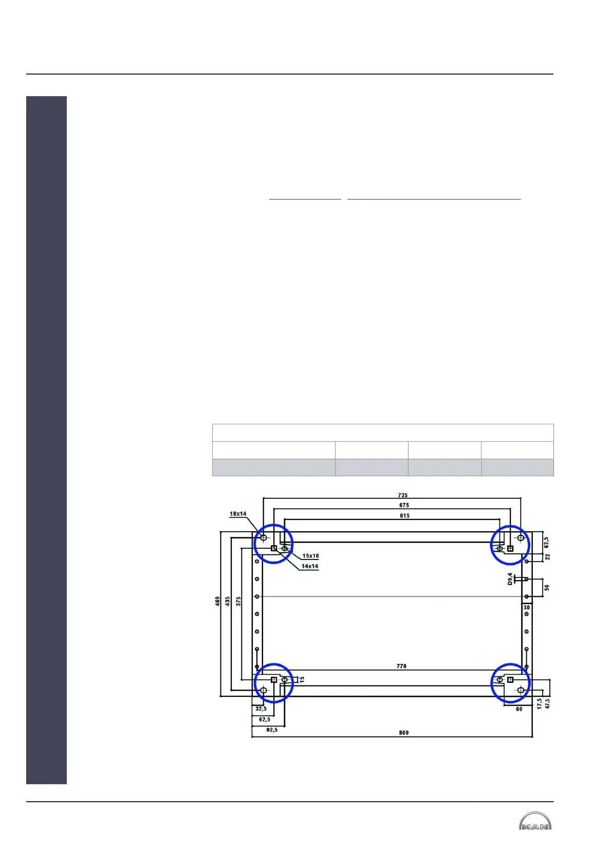
Table 14: Main dimensions of the control cabinet – VTA control system (VCS)
Figure 16: Bottom flange of the control cabinet base
The possible fastening holes are indicated here.
Control cabinet
Main dimensions
Bottom flange
5 Engine room planning
5.2 VTA Control System (VCS)
2013-12-04 - de
5
MAN Diesel & Turbo
24 (38)
EN-US