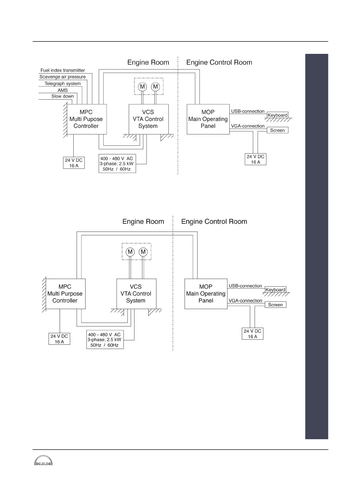
Figure 11: Wiring diagram – VTA control system (VCS) on MC/MC-C two-stroke engine
With this variant, the MPC responsible for the VTA control system (VCS) is
electronically integrated into the engine control system (ECS) and controlled
by it.
Figure 12: Wiring diagram – VTA control system (VCS) on ME/ME-C/ME-B two-stroke engine
With this variant, the VTA control system is completely integrated into the
engine control system. Engine and turbocharger are supplied as an opera-
tional unit.
The stand-alone solution can work independently of other control systems.
Various system parameters are monitored, on the basis of which the VTA is
adjusted using preset parameter sets.
VTA on ME/ME-C/ME-B
two-stroke engine
VTA on MAN Diesel
four-stroke engine
Stand-alone
2013-12-04 - de
4 Systems
4.1 VTA Control (VCS)
MAN Diesel & Turbo
4
EN-US
19 (38)