22
solutions creator
DIDO 26 MV
ITALIANO ENGLISH
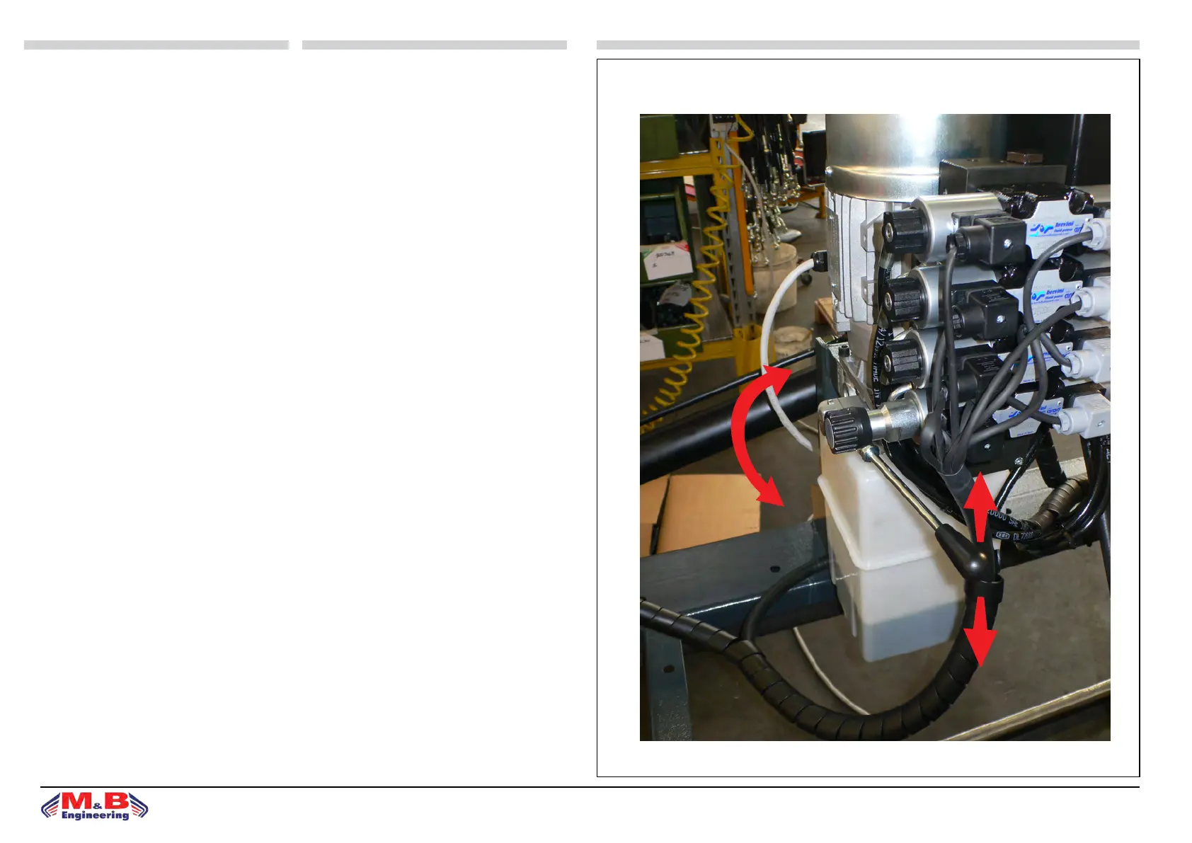
AZIONAMENTO DI EMERGENZA
La manovra di emergenza assicura che in caso di
avaria dell’impianto elettrico, la macchina possa
tornare in posizione di completa chiusura per po-
tersi muovere in sicurezza con il mezzo di traspor-
to no a destinazione.
Essa comprende una valvola selettrice di apertura e
chiusura manuale A.
Ruotando la valvola in senso orario, la valvola
chiude il contatto e permette mediante l’aziona-
mento manuale ripetuto della leva B, la chiusura
del relativo movimento macchina.
Nell’ordine:
• L’elettrovalvola 1 aziona la chiusura del ribal-
tamento macchina.
• L’elettrovalvola 2 comanda l’alzata e la discesa
in senso verticale del carrello portamandrino.
• L’elettrovalvola 3 comanda la traslazione in
senso orizzontale del carrello portamandrino.
Per selezionare il tipo di movimento, bisogna
smontare il coperchio in plastica posto all’estremità
dell’elettrovalvola come in gura, svitare la valvola
selettrice e avvitarla sull’elettrovalvola corrispon-
dente al movimento desiderato.
g.13
A
B
1
2
3
EMERGENCY ACTIVATION
e emergency manoeuvre ensures that in the event
of a fault with the electrical system the machine can
return to the completely closed position in order to
be safely moved with a means of transportation to
its destination.
is includes a manual opening and closing check
valve A.
By turning the valve clockwise it closes the contact
and allows, by the repeated manual activation of the
lever B, the relative machine movement to be closed.
In order:
Solenoid valve 1 activates closing of the machine til-
ting.
Solenoid valve 2 commands vertical liing and lo-
wering of the spindle holder trolley.
Solenoid valve 3 commands horizontal liing and
lowering of the spindle holder trolley.
To select the type of movement the plastic cover lo-
cated on the end of the solenoid valve must be re-
moved as shown in the illustration, the check valve
must be unscrewed on the solenoid valve that corre-
sponds to the desired movement.