25
solutions creator
DIDO 26 MV
ITALIANO ENGLISH
VERSIONI DOTATE DI EQUILIBRATRICE
WB290
ISTRUZIONI PER L’USO
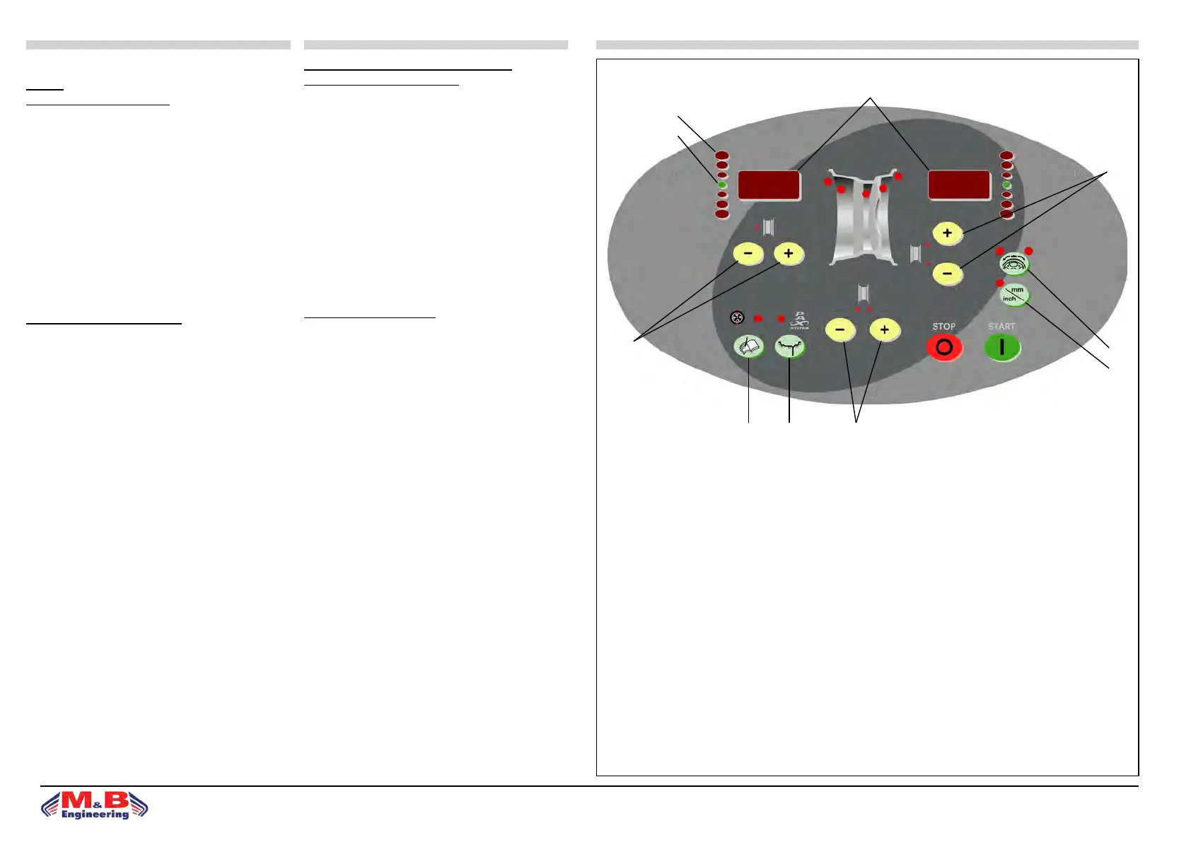
PANNELLO COMANDI - LEGENDA
1. Visualizzatore dati
2. Diodi luminosi di direzione punto di squilibrio
3. Punto di squilibrio (LED)
4. Tasti impostazione distanza cerchio
5. Tasti impostazione diametro cerchio
6. Tasti impostazione larghezza cerchio
7. Tasto SPLIT
8. Sel. unità di misura per largh.o diam.cerchio(mm/inch)
9. Tasto funzioni di controllo (MENÙ)
10. Tasto selezione programma di equilibratura (MODE)
EQUILIBRATURA RUOTE
Accendere la macchina mediante l’interruttore principale.
• All’accensione la macchina visualizza l’indicazione della
versione soware per alcuni sec; al termine i visualizzatori
(g.15) (1) evidenziano 0 0.
• Montare la ruota sulla macchina centrandola sull’apposita
angia e serrandola accuratamente.
• Per equilibrare la ruota occorre inserire i seguenti dati:a)
selezione del tipo di ruota e del programma di equilibratura
che denisce il posizionamento dei contrappesi sul cerchio.
b)impostazione delle misure della ruota: larghezza nomi-
nale e diametro nominale.
c)impostazione della distanza tra la macchina ed il an-
co interno del cerchio (vedi paragrafo “Impostazione dati
ruota”).
• Durante la fase di misura si spengono le letture eccetto un
segmento centrale nel visualizzatore.
• La grandezza e posizione degli squilibri dei due lati della
ruota vengono determinati in un unico lancio di misura, e
sono indicati separatamente sui visualizzatori.
• Il tasto di arresto STOP (g.15) ha la funzione di bloccare
la macchina in caso di emergenza.
• La grandezza e posizione degli squilibri dei due lati della
ruota vengono determinati in un unico lancio di misura, e
sono indicati separatamente sui visualizzatori: a sinistra è
indicato lo squilibrio del anco interno della ruota (rivolto
verso la macchina) e a destra quello del anco esterno.
WHEEL BALANCER VERSION WB290
INSTRUCTIONS FOR USE
CONTROL PANEL - KEY
1. Data display
2. Unbalance point direction LED luminous diodes.
3. Unbalance point (LED)
4. Rim distance setting key
5. Rim diameter setting key
6. Rim width setting key
7. SPLIT key
8. Selection key for rim width or diam.(mm/inch)
9. Control functions key (MENÙ)
10. Balancing program selection key (MODE)
WHEEL BALANCING
row main switch to activate machine.
• For a few seconds the monitor will display the soware
version installations. On completion of start-up the di-
splays (g.15) (1) indicate 0 0.
• Mount the wheel on the machine, centring it using the
special ange and locking it down carefully.
• To balance the wheel input the following data:
a)select type of wheel and balancing program for dening
positioning of counterweights on the rim (see section “Se-
lection of balancing program”).
b)set wheel measurements: rated width and rated diameter
(see section “Setting wheel data”).
c)set the distance between the machine and the internal
side of the rim (see section “Setting wheel data”).
• During the measuring operation, most of the readings are
switched o except for the central segment of the display.
• e size and position of the unbalances on the two sides
of the wheel are determined in a single measuring opera-
tion, and are separately indicated on the displays.
• e STOP (g.15) key blocks the machine in emergen-
cies.
• e size and position of the unbalances on the two sides
of the wheel are determined in a single measuring run, and
are separately indicated on the displays: wheel internal side
unbalance is indicated on the le(facing the machine) and
external side unbalance is indicated on the right.
g.15
1
2
3
4
5
6109
7
8